Solar and battery single line diagrams
A solar single line diagram shows how a PV system connects to the building’s electrical service: the array, the inverter or microinverters, the AC disconnect, the point of connection, the main panel and the meter. Utilities ask for it with an interconnection application and building departments ask for it with the permit, because it shows where the system backfeeds the service and how it is disconnected.
These templates cover load-side connections through a backfed breaker, supply-side connections ahead of the main, microinverter systems, hybrid inverters with a backup panel, and battery storage with partial or whole-home backup. Each one carries the busbar and continuous-current arithmetic in its notes, so you can replace the numbers with your own.
9 solar and battery single line diagram templates
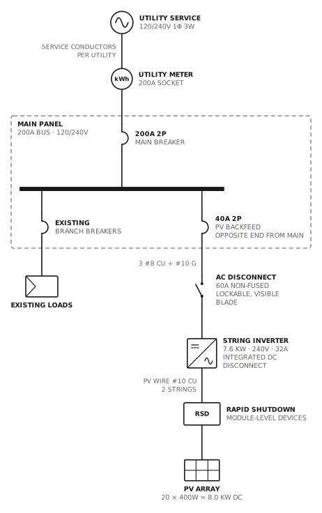
Grid-tied PV, string inverter
Load-side connection through a 40A backfed breaker.
Solar · storageView drawing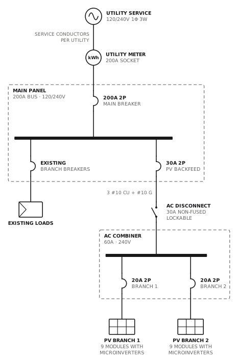
Grid-tied PV, microinverters
Two microinverter branches combined in an AC combiner.
Solar · storageView drawing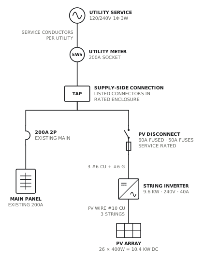
PV supply-side connection
Line-side tap with a fused, service-rated PV disconnect.
Solar · storageView drawing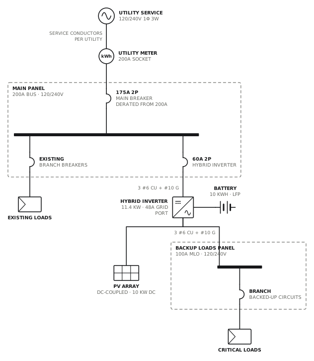
PV and storage, hybrid inverter
DC-coupled battery with a backup loads panel.
Solar · storageView drawing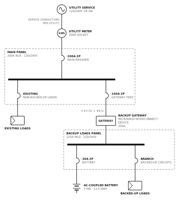
Battery with partial home backup
Backup gateway and a dedicated backup loads panel.
Solar · storageView drawing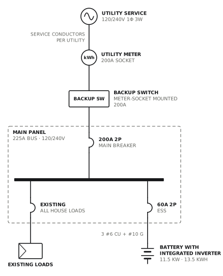
Battery with whole-home backup switch
Meter-socket backup switch islands the whole panel.
Solar · storageView drawing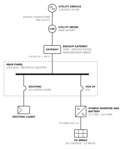
Battery and PV with whole-home gateway
Service-rated gateway ahead of the main panel.
Solar · storageView drawing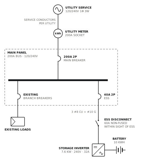
Storage system, 10 kW or less
Grid-interactive storage inverter on a 40A breaker.
Solar · storageView drawing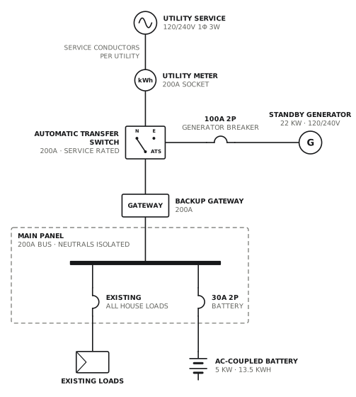
Battery with independent standby generator
Generator transfer switch upstream of the battery gateway.
Solar · storageView drawingWhat the reviewer looks for
- The point of connection: load side through a backfed breaker, or supply side ahead of the main.
- The busbar check for a load-side connection. Under the NEC it reads like this: 200A bus × 120% = 240A ≥ 200A main + 40A PV breaker.
- Inverter output current × 125%, and the breaker or fuse that protects it.
- The AC disconnect, its rating and where it is relative to the meter.
- Rapid shutdown, and for storage the gateway or transfer device that isolates backup loads from the grid.
The ratings on the templates are typical values, not a design for your job. Confirm what your authority having jurisdiction and your utility expect before you submit.
Questions about solar and battery drawings
What is a single line diagram for solar?
It is a one-line drawing of the PV system and the service it connects to. It shows the array size, the inverter and its output rating, the disconnects, the overcurrent protection, the conductor sizes, the point of connection to the service and the utility meter. Utilities and permit offices use it to check the interconnection.
Do I need a single line diagram or a three-line diagram for solar?
A single line diagram is enough for most residential interconnection applications. Some utilities ask for a three-line diagram, which draws every phase conductor, the neutral and the ground separately, for larger or three-phase systems. The utility’s interconnection requirements say which one it wants.
What is the 120% rule shown on solar single line diagrams?
It is the busbar check for a load-side connection in NEC 705.12 (2020 and 2023 editions). The main breaker rating plus 125% of the inverter output current may add up to 120% of the busbar rating, provided the solar breaker is at the opposite end of the bus from the main. A 200A bus allows 240A, so a 200A main leaves room for a 40A solar breaker. This is the United States rule. Canadian installations follow the interconnection rules in Section 64 of the Canadian Electrical Code instead.
Other single line diagram templates
Draw yours now
Free, in the browser, no account. Start from a template or describe the job in plain words, edit the drawing and export a PDF.