What is a single line diagram (one-line diagram)?
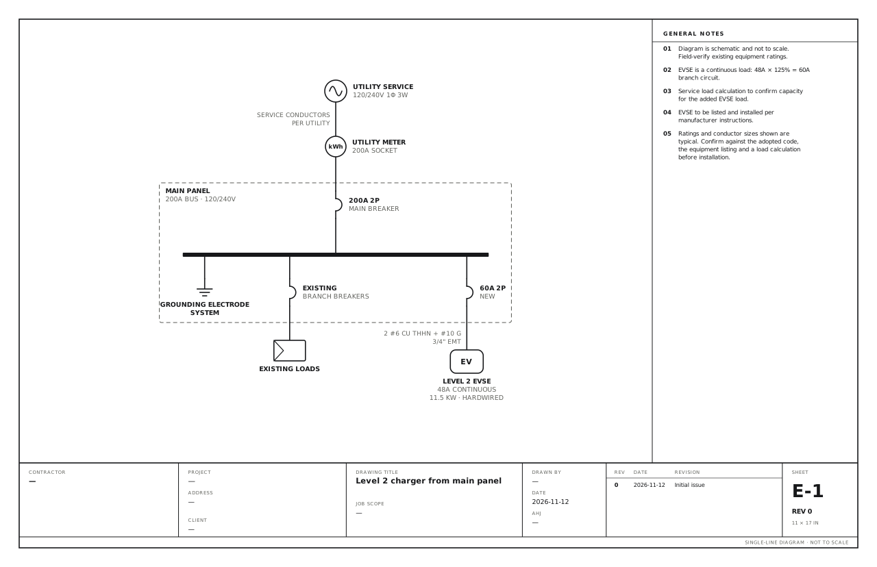
A single line diagram (SLD), also called a one-line diagram, is a simplified drawing of an electrical power system. One line stands for each set of conductors, whether that is two wires or five, and standard symbols stand for the equipment: the utility service, meters, transformers, breakers, switches, panels and loads. It shows how power gets from the source to every load, and what protects and disconnects it on the way.
| Also called | One-line diagram, single-line drawing, electrical one-line, SLD |
|---|---|
| Shows | Sources, service equipment, protection, panels, feeders and loads, with their ratings and conductor sizes |
| Leaves out | Physical locations, individual phase wires and control wiring |
| Used for | Permit applications, utility interconnection, design, fault and arc-flash studies, maintenance |
| Symbols | IEEE Std 315-1975 (also ANSI Y32.2 and CSA Z99) in North America; IEC 60617 elsewhere |
| Read | Top to bottom, from the source to the loads |
Why it is called a single line diagram
A three-phase feeder has three phase conductors, often a neutral, and a ground. Drawing all five for every feeder would bury the layout of the system. A single line diagram draws the whole feeder as one line and writes what it contains beside it, for example “4 #3/0 Cu, #6 Cu ground, 2 in EMT”. That is how a building’s whole distribution system fits on one sheet.
What a single line diagram shows
- Sources. The utility service with its voltage, phases and wires, plus any generators, PV arrays and batteries.
- Service equipment. The meter, the service disconnect and the main breaker, with their amp ratings.
- Distribution. Panels and switchboards with their bus ratings, and transformers with their kVA and voltages.
- Protection. Every breaker and fuse, with its amp rating and number of poles.
- Conductors. A callout on each feeder giving the size, the material and the raceway.
- Loads. Large loads drawn one by one, such as EV chargers, motors and HVAC units, and the rest grouped.
- Grounding and bonding. The grounding electrode system and where the neutral is bonded.
- Notes. The calculations and conditions the drawing depends on.
Single line diagram vs three-line, schematic and wiring diagrams
A single line diagram is not to scale and does not show where equipment sits in the building. It does not show individual phase wires, terminal numbers or control circuits. Those belong on other drawings.
| Drawing | What it shows | Used for |
|---|---|---|
| Single line (one-line) diagram | The whole power system, one line per circuit, with ratings | Permits, interconnection, studies, an overview of the system |
| Three-line diagram | Each phase, the neutral and the ground drawn separately | Metering, protection and transformer connections; some solar interconnections |
| Schematic (elementary) diagram | The logic of a control circuit, device by device | Designing and troubleshooting controls |
| Wiring diagram | Physical terminals and the wires between them | Building and wiring equipment |
| Riser diagram | A single line diagram arranged by floor | Multi-storey buildings |
| Panel schedule | Every circuit in one panel, with its load | Load calculations and panel directories |
How to read a single line diagram
- Start at the source. The utility is normally at the top of the sheet, and power flows down.
- Follow the line to the meter and the service disconnect. The rating beside the main breaker is the size of the service.
- Find the buses. A heavy bar is a bus. Everything tapped from it is fed by that panel or switchboard.
- Read each label. A breaker marked “60A 2P” is a 60 amp, two-pole breaker. A transformer is marked with its kVA and both voltages.
- Read the conductor callouts on the lines between devices.
- Look at the enclosures. A dashed box groups the devices that share an enclosure, such as a main breaker and its panel.
- Read the notes and the title block. The notes carry the calculations. The title block says which job, which sheet and which revision.
Common single line diagram symbols
A handful of symbols cover most drawings. The full symbol chart covers 24 of them with how each one is labelled.
- Utility source
- Meter
- Circuit breaker
- Disconnect switch
- Fused disconnect
- Transformer
- Transfer switch
- Generator
- Inverter
- Ground
When you need a single line diagram
- Permit applications. Service upgrades, EV chargers, generators, subpanels and tenant fit-ups are commonly submitted with a single line diagram.
- Utility interconnection. Solar and battery applications need one to show the point of connection and the disconnects.
- Commercial design. It is the base drawing for load, fault current, coordination and arc-flash studies.
- Maintenance and safety. NFPA 70E requires that a single line diagram, where one is provided for the electrical system, be kept legible and current (section 205.3 in the 2024 edition, 205.2 in the 2021 edition and earlier).
Requirements differ between jurisdictions and utilities. Ask your authority having jurisdiction (AHJ) what it wants on the drawing before you start.
Single line diagram examples
These are complete drawings with typical ratings, conductor callouts and notes. All 40 are free to open and edit: see every example and template.
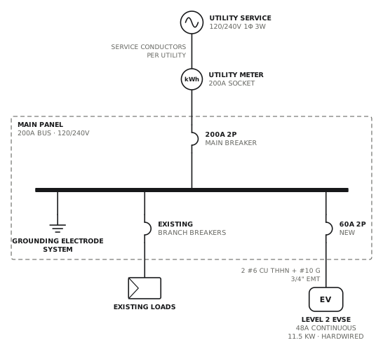
Level 2 charger from main panel
Dedicated 60A circuit to a hardwired 48A charger.
EVView drawing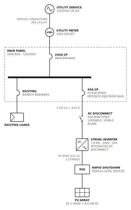
Grid-tied PV, string inverter
Load-side connection through a 40A backfed breaker.
Solar · storageView drawing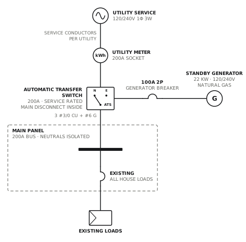
Standby generator, whole-home ATS
Service-rated 200A automatic transfer switch.
GeneratorView drawing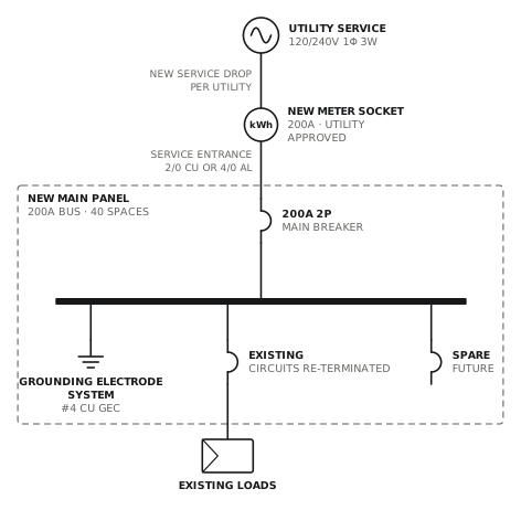
Service and main panel upgrade to 200A
New meter socket, service entrance and 200A panel.
ServiceView drawing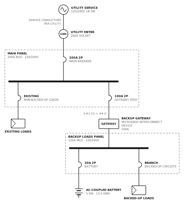
Battery with partial home backup
Backup gateway and a dedicated backup loads panel.
Solar · storageView drawing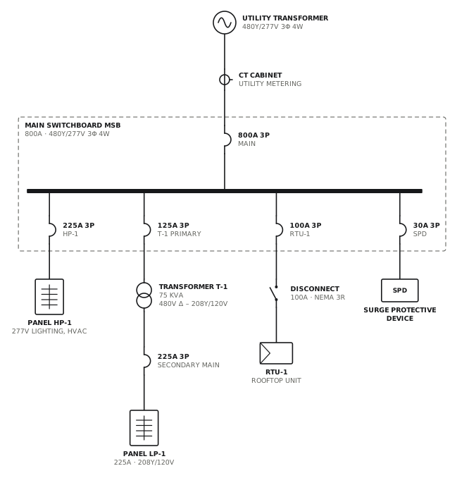
480Y/277V service with 208V transformer
800A switchboard with a 75 kVA transformer for 120/208V loads.
CommercialView drawing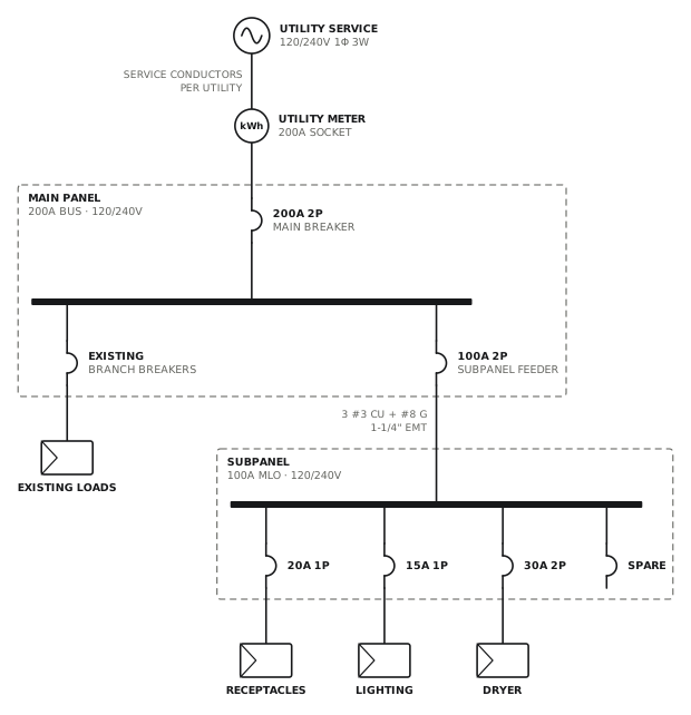
Subpanel addition
100A four-wire feeder to a new subpanel.
ServiceView drawing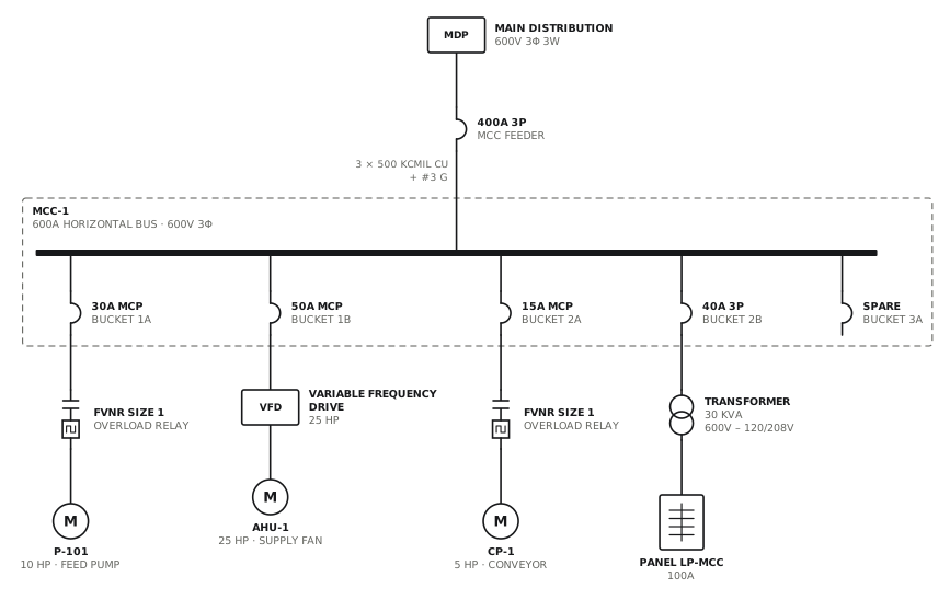
Motor control centre
MCC with starters, a drive, a lighting transformer and a spare bucket.
CommercialView drawingHow to make a single line diagram
Start with the source at the top, draw the meter, the service disconnect and the main panel in the order power flows through them, then add each feeder and large load as a branch from the panel bus. Label every device with its rating and every line with its conductors, then add the grounding, the notes and a title block. The step-by-step guide goes through it with an example.
Questions about single line diagrams
What does SLD stand for in electrical work?
SLD stands for single line diagram. It is the one-line drawing of an electrical power system. Single line diagram, single-line diagram, one-line diagram and SLD all name the same drawing.
Is a single line diagram the same as a one-line diagram?
Yes. They are two names for the same drawing. “One-line diagram” is heard more in the United States, and “single line diagram” or “SLD” more in Canada, the UK, Australia and India.
What is the difference between a single line diagram and a three-line diagram?
A single line diagram draws each circuit as one line, whatever the number of wires. A three-line diagram draws every phase conductor, the neutral and the ground separately, so it can show metering, protection and transformer connections wire by wire. The single line is the overview and the three-line is the detail.
What is the difference between a single line diagram and a wiring diagram?
A single line diagram shows what is connected to what and at what rating. A wiring diagram shows the physical connections: each terminal and each wire between them. You plan and get a permit with the single line diagram, and you build from the wiring diagram.
What should a single line diagram include for a permit?
The service voltage, phase and amp rating; the meter; the service disconnect and main breaker; each panel with its bus rating; the breakers and fuses with their ratings; conductor sizes and raceways; transformers, generators, inverters and large loads with their ratings; the grounding electrode system; and a title block with the address, the contractor, the date and the revision. Many reviewers also want the calculations in the notes.
Who can draw a single line diagram?
It depends on the jurisdiction and the size of the job. Many permit offices accept a single line diagram drawn by the electrical contractor for residential and small commercial work. Larger services, many commercial buildings and some utility interconnections need drawings sealed by a licensed professional engineer. Ask your authority having jurisdiction.
Is a single line diagram required by code?
Not for every installation. It is usually the permit office or the utility that asks for one. NEC 215.5 (2023 edition) lets the authority having jurisdiction require a diagram of the feeders before installation, and Rule 2-014 of the Canadian Electrical Code covers the plans and specifications an inspection department can require. NFPA 70E (section 205.3 in the 2024 edition, 205.2 in the 2021 edition and earlier) requires that a single line diagram, where one exists, be kept legible and current.
What software is used to draw single line diagrams?
Engineers commonly use CAD programs such as AutoCAD, and power system analysis software such as ETAP, SKM PowerTools or EasyPower when the drawing feeds a study. General diagram tools such as Visio and draw.io work with a symbol library. Oneline is a free browser tool for the contractor’s permit drawing: it starts from a template or a written description of the job and exports a PDF.
Do I need a single line diagram for solar panels?
In most places, yes. Utilities ask for a single line diagram with the interconnection application, and building departments ask for one with the permit. It shows the array, the inverter, the disconnects, the point of connection and the meter.
How do I make a single line diagram for free?
Open Oneline at singlelinediagrams.com, pick the template closest to your job or describe the job in a sentence, change the ratings and labels, fill in the title block and export a PDF. There is no account and no charge.
References and editions
Code references on this site are to the 2023 National Electrical Code (NFPA 70) and the 2024 Canadian Electrical Code, Part I (CSA C22.1). Section numbers move between editions, and each state, province and city adopts its own edition with its own amendments, so check the one in force where you work. These are model codes and standards: what is law is what your jurisdiction has adopted.
- NFPA 70, National Electrical Code, section 215.5, Diagrams of Feeders.
- CSA C22.1, Canadian Electrical Code, Part I, Rule 2-014, Plans and specifications.
- NFPA 70E, Standard for Electrical Safety in the Workplace, Single-Line Diagram: section 205.3 in the 2024 edition, 205.2 in the 2021 edition and earlier.
- EV charging and energy management, on the EV charger drawings: NEC 625.42, 220.70 and 750.30; CEC Rule 8-106.
- Solar and storage interconnection, on the solar and battery drawings: NEC 705.11 (supply-side connections), 705.12 (load-side connections and the 120% busbar check) and 690.12 (rapid shutdown); CEC Section 64, including Rule 64-218.
- Fire pumps: NEC Article 695 and NFPA 20; CEC Section 32.
- IEEE Std 315-1975, Graphic Symbols for Electrical and Electronics Diagrams (also ANSI Y32.2 and CSA Z99). IEEE lists it as inactive, and it is still the common reference for North American one-line symbols.
- IEC 60617, Graphical symbols for diagrams.
Draw yours now
Free, in the browser, no account. Start from a template or describe the job in plain words, edit the drawing and export a PDF.