Rooftop PV riser, microinverters single line diagram
Roof array with microinverters, combiner and disconnect on the exterior wall, backfed breaker in the garage panel.
A free template with typical ratings, conductor callouts and general notes. Open it, change what differs on your job, fill in the title block and export a PDF.
Open this template in the editor Download the SVG
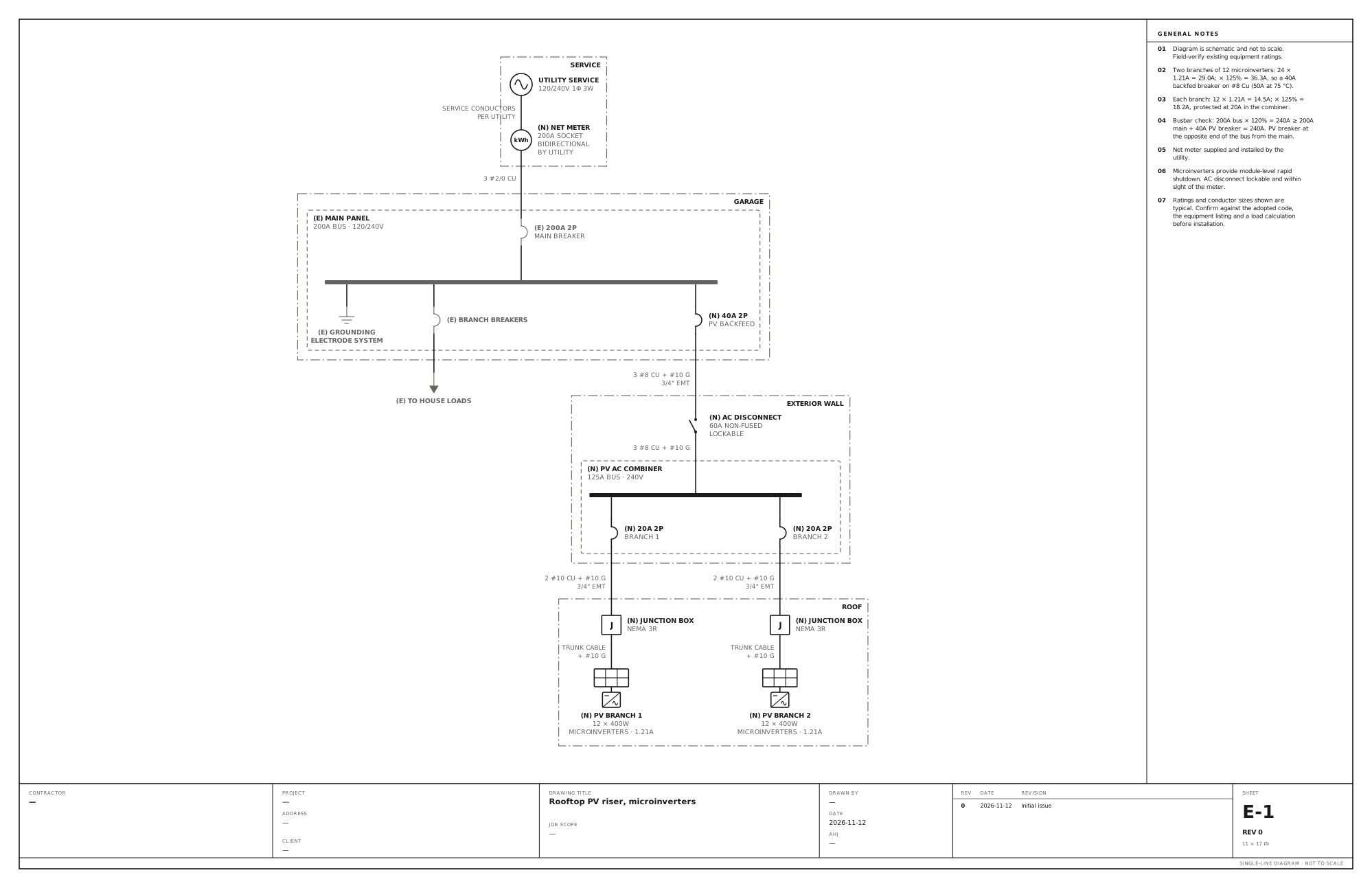
What the drawing shows
Every device on the sheet, in the order power reaches it.
| Symbol | Label | Rating or detail | Conductors feeding it |
|---|---|---|---|
| Utility source | Utility service | 120/240V 1φ 3W | |
| Meter | Net meter | 200A socket · bidirectional, by utility | Service conductors, per utility |
| Circuit breaker | 200A 2P | Main breaker | 3 #2/0 Cu |
| Panel | Main panel | 200A bus · 120/240V | |
| Ground | Grounding electrode system | ||
| Circuit breaker | Branch breakers | ||
| To (continues off sheet) | To house loads | ||
| Circuit breaker | 40A 2P | PV backfeed | |
| Disconnect switch | AC disconnect | 60A non-fused · lockable | 3 #8 Cu + #10 G, 3/4" EMT |
| Panel | PV AC combiner | 125A bus · 240V | 3 #8 Cu + #10 G |
| Circuit breaker | 20A 2P | Branch 1 | |
| Junction box | Junction box | NEMA 3R | 2 #10 Cu + #10 G, 3/4" EMT |
| Module with microinverter | PV branch 1 | 12 × 400W, microinverters · 1.21A | Trunk cable, + #10 G |
| Circuit breaker | 20A 2P | Branch 2 | |
| Junction box | Junction box | NEMA 3R | 2 #10 Cu + #10 G, 3/4" EMT |
| Module with microinverter | PV branch 2 | 12 × 400W, microinverters · 1.21A | Trunk cable, + #10 G |
Notes on the sheet
- Two branches of 12 microinverters: 24 × 1.21A = 29.0A; × 125% = 36.3A, so a 40A backfed breaker on #8 Cu (50A at 75 °C).
- Each branch: 12 × 1.21A = 14.5A; × 125% = 18.2A, protected at 20A in the combiner.
- Busbar check: 200A bus × 120% = 240A ≥ 200A main + 40A PV breaker = 240A. PV breaker at the opposite end of the bus from the main.
- Net meter supplied and installed by the utility.
- Microinverters provide module-level rapid shutdown. AC disconnect lockable and within sight of the meter.
Diagram is schematic and not to scale. Field-verify existing equipment ratings. Ratings and conductor sizes shown are typical. Confirm against the adopted code, the equipment listing and a load calculation before installation. Code references are to the 2023 NEC and the 2024 Canadian Electrical Code: see references and editions.
Related solar and battery drawings
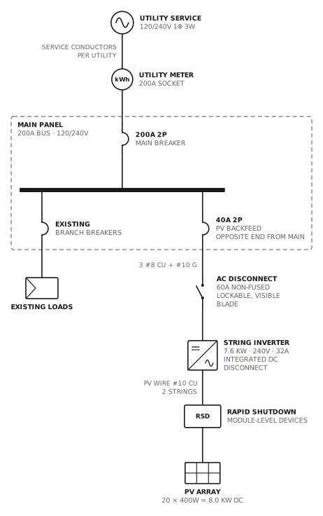
Grid-tied PV, string inverter
Load-side connection through a 40A backfed breaker.
Solar · storageView drawing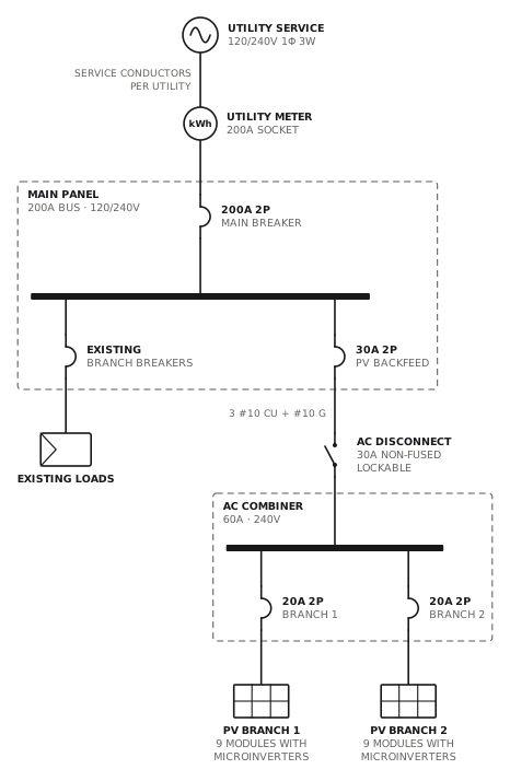
Grid-tied PV, microinverters
Two microinverter branches combined in an AC combiner.
Solar · storageView drawing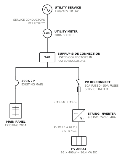
PV supply-side connection
Line-side tap to a fused, service-rated PV disconnect.
Solar · storageView drawing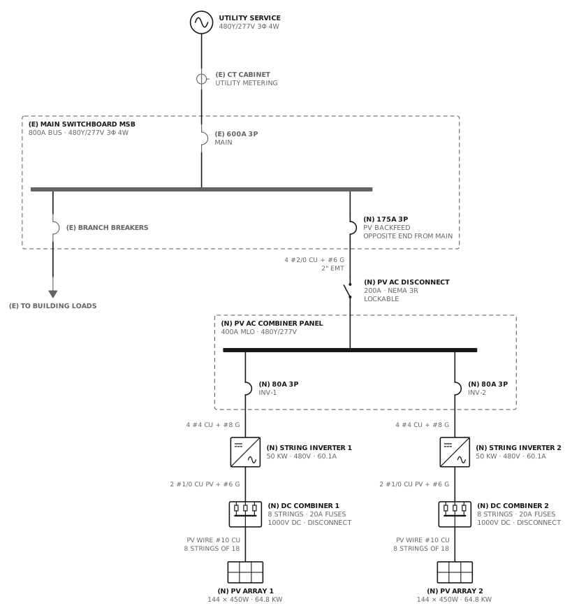
Commercial rooftop PV, string inverters
DC combiners and two 50 kW inverters into an AC combiner panel, backfed at the switchboard.
Solar · storageView drawingSee all solar and battery single line diagrams, or all 52 templates.
Start from this drawing
Free, in the browser, no account. Start from a template or describe the job in plain words, edit the drawing and export a PDF.