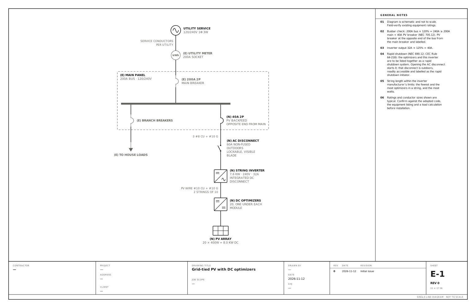
Grid-tied PV with DC optimizers single line diagram
An optimizer under each module, two strings to one inverter, backfed at the main panel. Use this for a string inverter with a DC optimizer under each module. The optimizers are drawn between the array and the inverter, because they are part of the rapid shutdown system and they set how the strings are laid out.
A free template with typical ratings, conductor callouts and general notes. Open it, change what differs on your job, fill in the title block and export a PDF.
Open this template in the editor Download the SVG
What the reviewer checks on this drawing
The reviewer checks the busbar arithmetic, the inverter output at 125%, the string lengths against the inverter manufacturer’s limits, and that the optimizers and the inverter are listed together for rapid shutdown, with the initiator labelled.
What the drawing shows
Every device on the sheet, in the order power reaches it.
| Symbol | Label | Rating or detail | Conductors feeding it |
|---|---|---|---|
| Utility source | Utility service | 120/240V 1φ 3W | |
| Meter | Utility meter | 200A socket | Service conductors, per utility |
| Circuit breaker | 200A 2P | Main breaker | |
| Panel | Main panel | 200A bus · 120/240V | |
| Circuit breaker | Branch breakers | ||
| To (continues off sheet) | To house loads | ||
| Circuit breaker | 40A 2P | PV backfeed, opposite end from main | |
| Disconnect switch | AC disconnect | 60A non-fused · outdoors, lockable, visible blade | 3 #8 Cu + #10 G |
| Inverter | String inverter | 7.6 kW · 240V · 32A, integrated DC disconnect | |
| DC/DC converter | DC optimizers | 20, one under each module | PV wire #10 Cu + #10 G, 2 strings of 10 |
| PV array | PV array | 20 × 400W = 8.0 kW DC |
Notes on the sheet
- Busbar check: 200A bus × 120% = 240A ≥ 200A main + 40A PV breaker (NEC 705.12). PV breaker at the opposite end of the bus from the main breaker and labelled.
- Inverter output 32A × 125% = 40A.
- Rapid shutdown (NEC 690.12; CEC Rule 64-218): the optimizers and this inverter are to be listed together as a rapid shutdown system. Opening the AC disconnect starts it; that disconnect is outdoors, readily accessible and labelled as the rapid shutdown initiator.
- String length within the inverter manufacturer’s limits: the fewest and the most optimizers in a string, and the most watts.
Diagram is schematic and not to scale. Field-verify existing equipment ratings. Ratings and conductor sizes shown are typical. Confirm against the adopted code, the equipment listing and a load calculation before installation. Code references are to the 2023 NEC and the 2024 Canadian Electrical Code: see references and editions.
Related solar and battery drawings
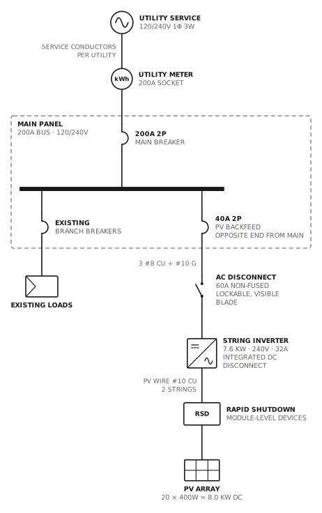
Grid-tied PV, string inverter
Load-side connection through a 40A backfed breaker.
Solar · storageView drawing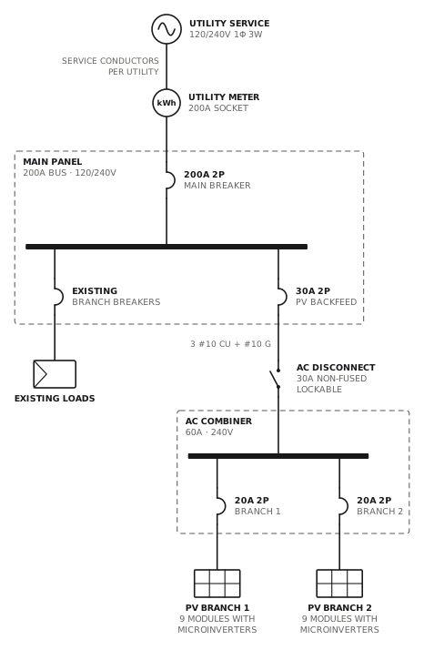
Grid-tied PV, microinverters
Two microinverter branches combined in an AC combiner.
Solar · storageView drawing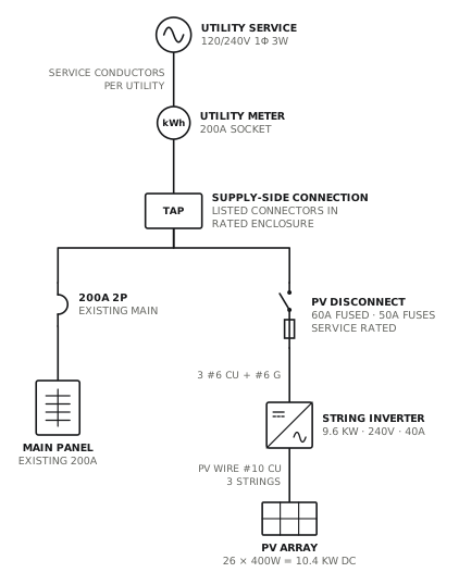
PV supply-side connection
Line-side tap to a fused, service-rated PV disconnect.
Solar · storageView drawing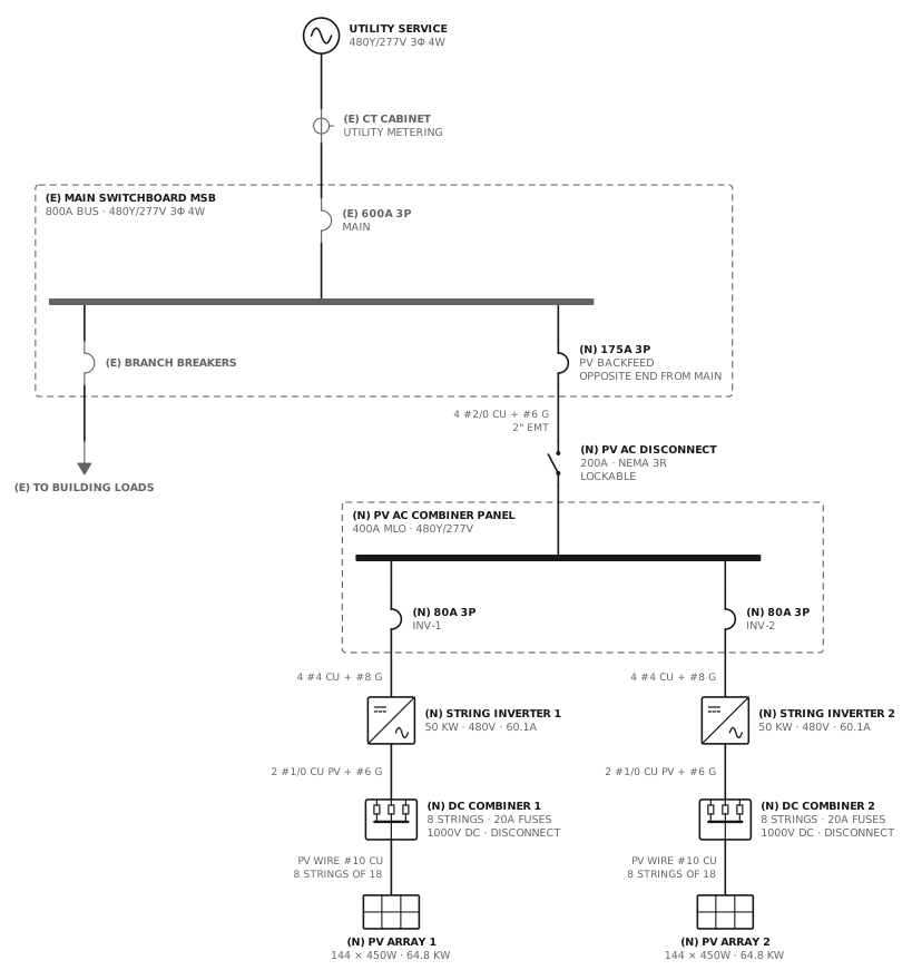
Commercial rooftop PV, string inverters
DC combiners and two 50 kW inverters into an AC combiner panel, backfed at the switchboard.
Solar · storageView drawingSee all solar and battery single line diagrams, or all 80 templates.
Start from this drawing
Free, in the browser, no account. Start from a template or describe the job in plain words, edit the drawing and export a PDF.