Off-grid PV with battery and generator single line diagram
Charge controller, 48V battery bank and an inverter-charger with a generator input. No utility.
A free template with typical ratings, conductor callouts and general notes. Open it, change what differs on your job, fill in the title block and export a PDF.
Open this template in the editor Download the SVG
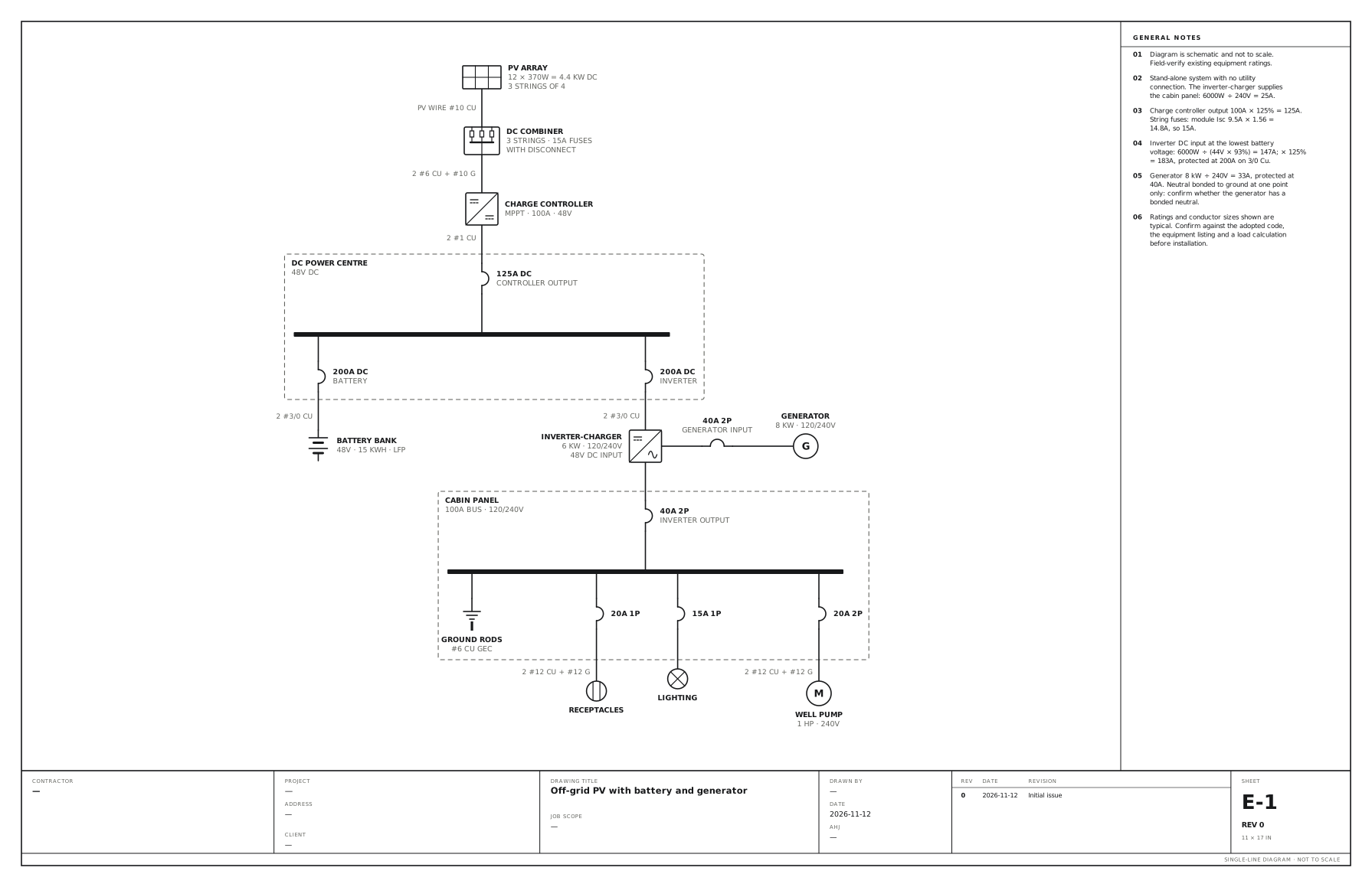
What the drawing shows
Every device on the sheet, in the order power reaches it.
| Symbol | Label | Rating or detail | Conductors feeding it |
|---|---|---|---|
| PV array | PV array | 12 × 370W = 4.4 kW DC, 3 strings of 4 | |
| PV combiner | DC combiner | 3 strings · 15A fuses, with disconnect | PV wire #10 Cu |
| DC/DC converter | Charge controller | MPPT · 100A · 48V | 2 #6 Cu + #10 G |
| Circuit breaker | 125A DC | Controller output | 2 #1 Cu |
| Panel | DC power centre | 48V DC | |
| Circuit breaker | 200A DC | Battery | |
| Battery | Battery bank | 48V · 15 kWh · LFP | 2 #3/0 Cu |
| Circuit breaker | 200A DC | Inverter | |
| Inverter | Inverter-charger | 6 kW · 120/240V, 48V DC input | 2 #3/0 Cu |
| Circuit breaker | 40A 2P | Generator input | |
| Generator | Generator | 8 kW · 120/240V | |
| Circuit breaker | 40A 2P | Inverter output | |
| Panel | Cabin panel | 100A bus · 120/240V | |
| Grounding electrode | Ground rods | #6 Cu GEC | |
| Circuit breaker | 20A 1P | ||
| Receptacle | Receptacles | 2 #12 Cu + #12 G | |
| Circuit breaker | 15A 1P | ||
| Lighting | Lighting | ||
| Circuit breaker | 20A 2P | ||
| Motor | Well pump | 1 HP · 240V | 2 #12 Cu + #12 G |
Notes on the sheet
- Stand-alone system with no utility connection. The inverter-charger supplies the cabin panel: 6000W ÷ 240V = 25A.
- Charge controller output 100A × 125% = 125A. String fuses: module Isc 9.5A × 1.56 = 14.8A, so 15A.
- Inverter DC input at the lowest battery voltage: 6000W ÷ (44V × 93%) = 147A; × 125% = 183A, protected at 200A on 3/0 Cu.
- Generator 8 kW ÷ 240V = 33A, protected at 40A. Neutral bonded to ground at one point only: confirm whether the generator has a bonded neutral.
Diagram is schematic and not to scale. Field-verify existing equipment ratings. Ratings and conductor sizes shown are typical. Confirm against the adopted code, the equipment listing and a load calculation before installation. Code references are to the 2023 NEC and the 2024 Canadian Electrical Code: see references and editions.
Related solar and battery drawings
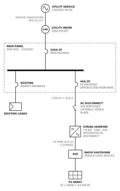
Grid-tied PV, string inverter
Load-side connection through a 40A backfed breaker.
Solar · storageView drawing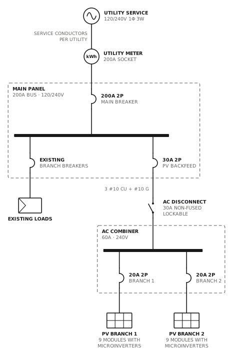
Grid-tied PV, microinverters
Two microinverter branches combined in an AC combiner.
Solar · storageView drawing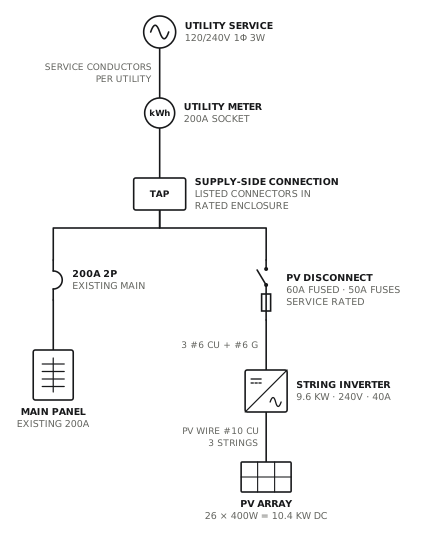
PV supply-side connection
Line-side tap to a fused, service-rated PV disconnect.
Solar · storageView drawing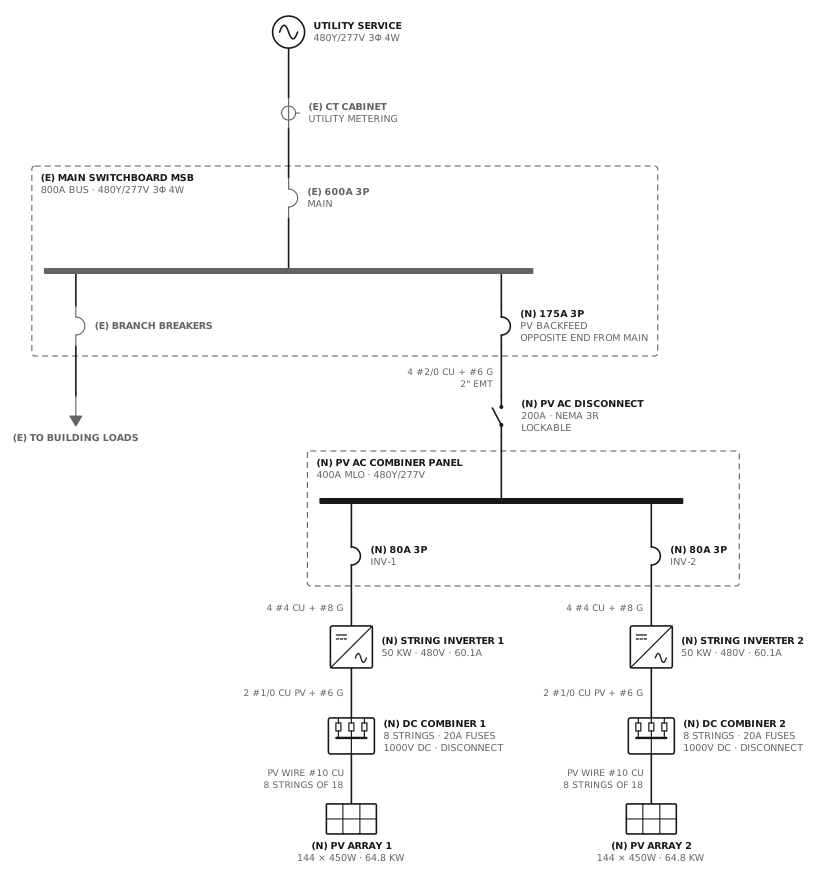
Commercial rooftop PV, string inverters
DC combiners and two 50 kW inverters into an AC combiner panel, backfed at the switchboard.
Solar · storageView drawingSee all solar and battery single line diagrams, or all 52 templates.
Start from this drawing
Free, in the browser, no account. Start from a template or describe the job in plain words, edit the drawing and export a PDF.