Commercial battery storage for peak shaving single line diagram
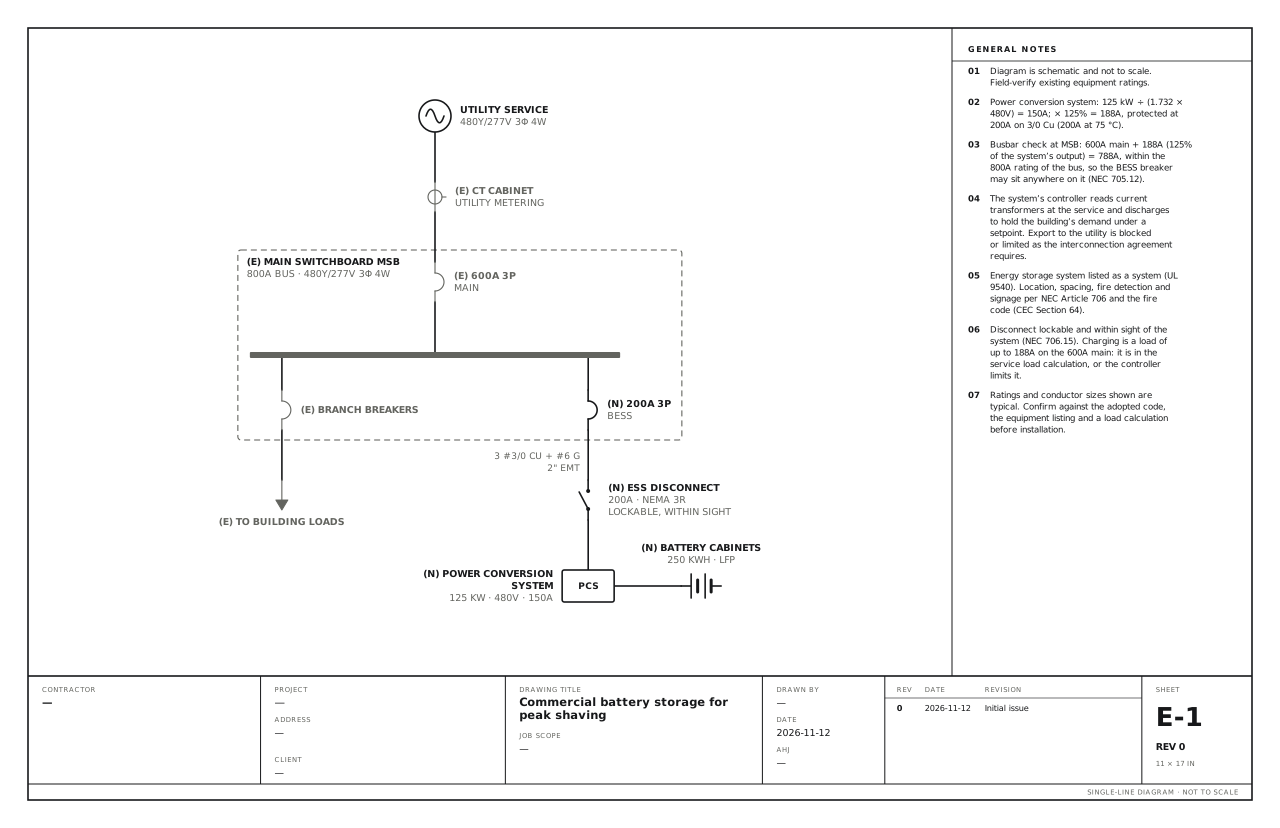
A 125 kW, 250 kWh battery system backfed at a 480V switchboard, discharging to hold down demand. Use this for a battery system added to a commercial building to cut demand charges. It connects through a breaker at the main switchboard and discharges when the building’s demand nears a setpoint.
A free template with typical ratings, conductor callouts and general notes. Open it, change what differs on your job, fill in the title block and export a PDF.
Open this template in the editor Download the SVG
What the reviewer checks on this drawing
The reviewer checks the output current at 125%, the busbar arithmetic at the switchboard, the disconnect within sight of the system, the system’s listing, and its location and fire protection. The utility checks how export is prevented or limited.
What the drawing shows
Every device on the sheet, in the order power reaches it.
| Symbol | Label | Rating or detail | Conductors feeding it |
|---|---|---|---|
| Utility source | Utility service | 480Y/277V 3φ 4W | |
| Current transformer | CT cabinet | Utility metering | |
| Circuit breaker | 600A 3P | Main | |
| Panel | Main switchboard MSB | 800A bus · 480Y/277V 3φ 4W | |
| Circuit breaker | Branch breakers | ||
| To (continues off sheet) | To building loads | ||
| Circuit breaker | 200A 3P | BESS | |
| Disconnect switch | ESS disconnect | 200A · NEMA 3R, lockable, within sight | 3 #3/0 Cu + #6 G, 2" EMT |
| Device | Power conversion system (PCS) | 125 kW · 480V · 150A | |
| Battery | Battery cabinets | 250 kWh · LFP |
Notes on the sheet
- Power conversion system: 125 kW ÷ (1.732 × 480V) = 150A; × 125% = 188A, protected at 200A on 3/0 Cu (200A at 75 °C).
- Busbar check at MSB: 600A main + 188A (125% of the system’s output) = 788A, within the 800A rating of the bus, so the BESS breaker may sit anywhere on it (NEC 705.12).
- The system’s controller reads current transformers at the service and discharges to hold the building’s demand under a setpoint. Export to the utility is blocked or limited as the interconnection agreement requires.
- Energy storage system listed as a system (UL 9540). Location, spacing, fire detection and signage per NEC Article 706 and the fire code (CEC Section 64).
- Disconnect lockable and within sight of the system (NEC 706.15). Charging is a load of up to 188A on the 600A main: it is in the service load calculation, or the controller limits it.
Diagram is schematic and not to scale. Field-verify existing equipment ratings. Ratings and conductor sizes shown are typical. Confirm against the adopted code, the equipment listing and a load calculation before installation. Code references are to the 2023 NEC and the 2024 Canadian Electrical Code: see references and editions.
Related solar and battery drawings
Grid-tied PV, string inverter
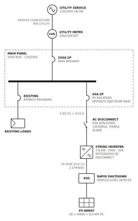
Load-side connection through a 40A backfed breaker.
Solar · storageView drawing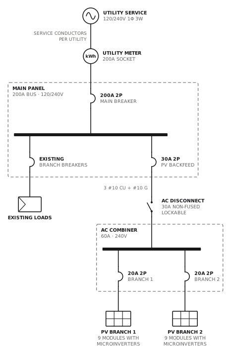
Grid-tied PV, microinverters
Two microinverter branches combined in an AC combiner.
Solar · storageView drawing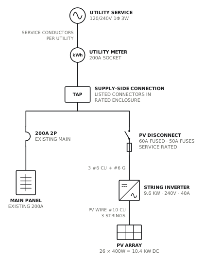
PV supply-side connection
Line-side tap to a fused, service-rated PV disconnect.
Solar · storageView drawing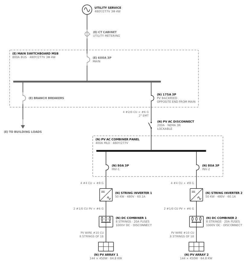
Commercial rooftop PV, string inverters
DC combiners and two 50 kW inverters into an AC combiner panel, backfed at the switchboard.
Solar · storageView drawingSee all solar and battery single line diagrams, or all 80 templates.
Start from this drawing
Free, in the browser, no account. Start from a template or describe the job in plain words, edit the drawing and export a PDF.