Parking lot lighting with contactor single line diagram
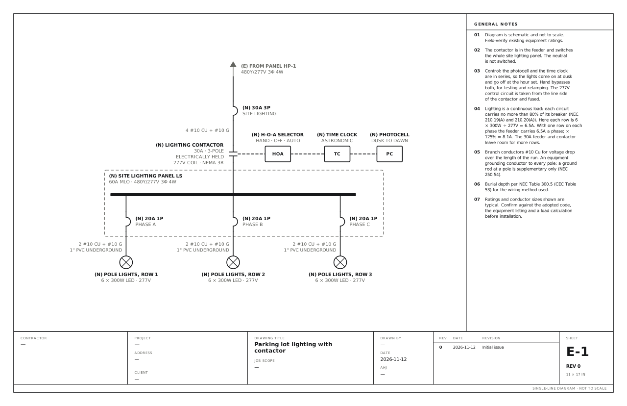
A lighting contactor under a photocell and a time clock switches a site lighting panel. Use this for parking lot or site lighting switched by a contactor under a photocell and a time clock, with a Hand-Off-Auto selector for testing.
A free template with typical ratings, conductor callouts and general notes. Open it, change what differs on your job, fill in the title block and export a PDF.
Open this template in the editor Download the SVG
What the reviewer checks on this drawing
The reviewer checks the contactor rating against the feeder it switches, where its control power comes from, that the neutral is not switched, the continuous load on each circuit, the conductor size against voltage drop, and the equipment ground to every pole.
What the drawing shows
Every device on the sheet, in the order power reaches it.
| Symbol | Label | Rating or detail | Conductors feeding it |
|---|---|---|---|
| From (continues off sheet) | From panel HP-1 | 480Y/277V 3φ 4W | |
| Circuit breaker | 30A 3P | Site lighting | |
| Contactor | Lighting contactor | 30A · 3-pole · electrically held, 277V coil · NEMA 3R | 4 #10 Cu + #10 G |
| Device | H-O-A selector (HOA) | Hand · Off · Auto | |
| Device | Time clock (TC) | Astronomic | |
| Device | Photocell (PC) | Dusk to dawn | |
| Panel | Site lighting panel LS | 60A MLO · 480Y/277V 3φ 4W | |
| Circuit breaker | 20A 1P | Phase A | |
| Lighting | Pole lights, row 1 | 6 × 300W LED · 277V | 2 #10 Cu + #10 G, 1" PVC underground |
| Circuit breaker | 20A 1P | Phase B | |
| Lighting | Pole lights, row 2 | 6 × 300W LED · 277V | 2 #10 Cu + #10 G, 1" PVC underground |
| Circuit breaker | 20A 1P | Phase C | |
| Lighting | Pole lights, row 3 | 6 × 300W LED · 277V | 2 #10 Cu + #10 G, 1" PVC underground |
Notes on the sheet
- The contactor is in the feeder and switches the whole site lighting panel. The neutral is not switched.
- Control: the photocell and the time clock are in series, so the lights come on at dusk and go off at the hour set. Hand bypasses both, for testing and relamping. The 277V control circuit is taken from the line side of the contactor and fused.
- Lighting is a continuous load: each circuit carries no more than 80% of its breaker (NEC 210.19(A) and 210.20(A)). Here each row is 6 × 300W ÷ 277V = 6.5A. With one row on each phase the feeder carries 6.5A a phase; × 125% = 8.1A. The 30A feeder and contactor leave room for more rows.
- Branch conductors #10 Cu for voltage drop over the length of the run. An equipment grounding conductor to every pole; a ground rod at a pole is supplementary only (NEC 250.54).
- Burial depth per NEC Table 300.5 (CEC Table 53) for the wiring method used.
Diagram is schematic and not to scale. Field-verify existing equipment ratings. Ratings and conductor sizes shown are typical. Confirm against the adopted code, the equipment listing and a load calculation before installation. Code references are to the 2023 NEC and the 2024 Canadian Electrical Code: see references and editions.
Related commercial and industrial drawings
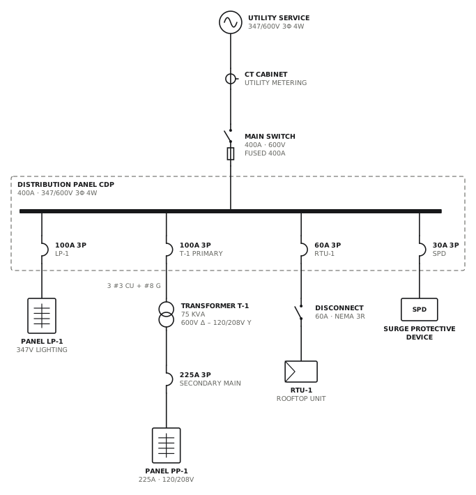
347/600V service with step-down transformer
Canadian commercial service with a 75 kVA transformer to 120/208V.
CommercialView drawing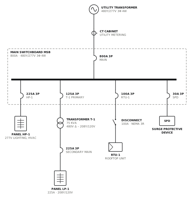
480Y/277V service with 208V transformer
800A switchboard with a 75 kVA transformer for 120/208V loads.
CommercialView drawing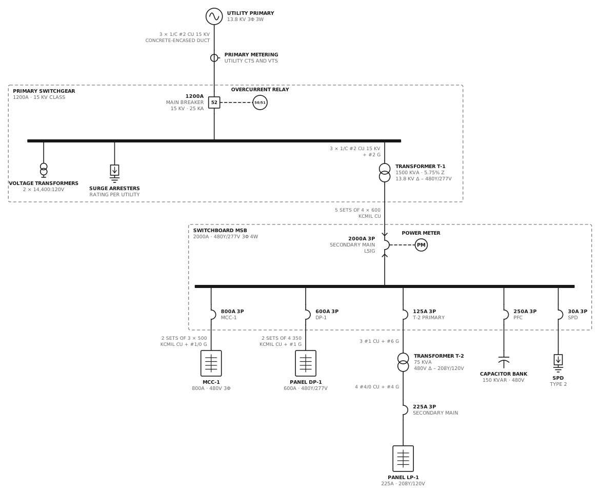
Medium-voltage service with unit substation
13.8 kV breaker with an overcurrent relay, a 1500 kVA transformer and a 2000A 480V switchboard.
CommercialView drawing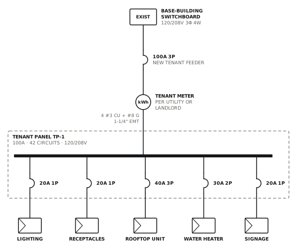
Tenant fit-up panel
New metered 100A feeder and panel from base-building distribution.
CommercialView drawingSee all commercial and industrial single line diagrams, or all 80 templates.
Start from this drawing
Free, in the browser, no account. Start from a template or describe the job in plain words, edit the drawing and export a PDF.