Medium-voltage service with unit substation single line diagram
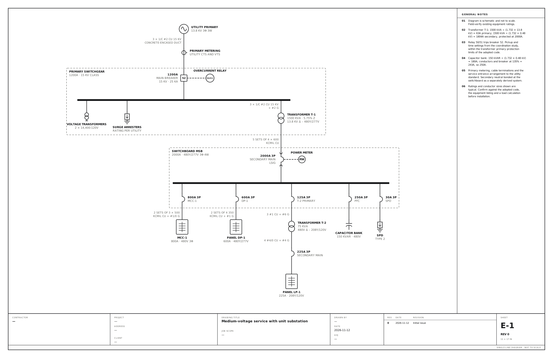
13.8 kV breaker with an overcurrent relay, a 1500 kVA transformer and a 2000A 480V switchboard.
A free template with typical ratings, conductor callouts and general notes. Open it, change what differs on your job, fill in the title block and export a PDF.
Open this template in the editor Download the SVG
What the drawing shows
Every device on the sheet, in the order power reaches it.
| Symbol | Label | Rating or detail | Conductors feeding it |
|---|---|---|---|
| Utility source | Utility primary | 13.8 kV 3φ 3W | |
| Current transformer | Primary metering | Utility CTs and VTs | 3 × 1/C #2 Cu 15 kV, concrete-encased duct |
| Power breaker | 1200A | Main breaker, 15 kV · 25 kA | |
| Protective relay | Overcurrent relay | ||
| Panel | Primary switchgear | 1200A · 15 kV class | |
| Voltage transformer | Voltage transformers | 2 × 14,400:120V | |
| Surge protective device | Surge arresters | Rating per utility | |
| Transformer | Transformer T-1 | 1500 kVA · 5.75% Z, 13.8 kV Δ – 480Y/277V | 3 × 1/C #2 Cu 15 kV, + #2 G |
| Draw-out breaker | 2000A 3P | Secondary main, LSIG | 5 sets of 4 × 600, kcmil Cu |
| Instrument | Power meter | ||
| Panel | Switchboard MSB | 2000A · 480Y/277V 3φ 4W | |
| Circuit breaker | 800A 3P | MCC-1 | |
| Panelboard | MCC-1 | 800A · 480V 3φ | 2 sets of 3 × 500, kcmil Cu + #1/0 G |
| Circuit breaker | 600A 3P | DP-1 | |
| Panelboard | Panel DP-1 | 600A · 480Y/277V | 2 sets of 4 350, kcmil Cu + #1 G |
| Circuit breaker | 125A 3P | T-2 primary | |
| Transformer | Transformer T-2 | 75 kVA, 480V Δ – 208Y/120V | 3 #1 Cu + #6 G |
| Circuit breaker | 225A 3P | Secondary main | 4 #4/0 Cu + #4 G |
| Panelboard | Panel LP-1 | 225A · 208Y/120V | |
| Circuit breaker | 250A 3P | PFC | |
| Capacitor bank | Capacitor bank | 150 kVAR · 480V | |
| Circuit breaker | 30A 3P | SPD | |
| Surge protective device | SPD | Type 2 |
Notes on the sheet
- Transformer T-1: 1500 kVA ÷ (1.732 × 13.8 kV) = 63A primary; 1500 kVA ÷ (1.732 × 0.48 kV) = 1804A secondary, protected at 2000A.
- Relay 50/51 trips breaker 52. Pickup and time settings from the coordination study, within the transformer primary protection limits of the adopted code.
- Capacitor bank: 150 kVAR ÷ (1.732 × 0.48 kV) = 180A; conductors and breaker at 135% = 243A, so 250A.
- Primary metering, cable terminations and the service entrance arrangement to the utility standard. Secondary neutral bonded at the switchboard as a separately derived system.
Diagram is schematic and not to scale. Field-verify existing equipment ratings. Ratings and conductor sizes shown are typical. Confirm against the adopted code, the equipment listing and a load calculation before installation. Code references are to the 2023 NEC and the 2024 Canadian Electrical Code: see references and editions.
Related commercial and industrial drawings
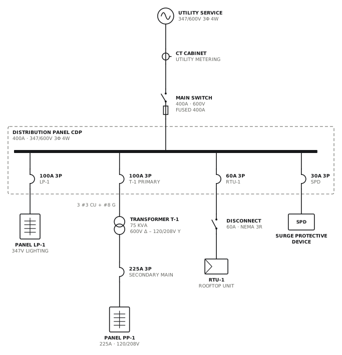
347/600V service with step-down transformer
Canadian commercial service with a 75 kVA transformer to 120/208V.
CommercialView drawing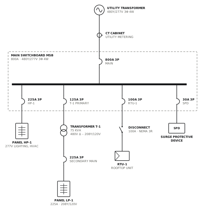
480Y/277V service with 208V transformer
800A switchboard with a 75 kVA transformer for 120/208V loads.
CommercialView drawing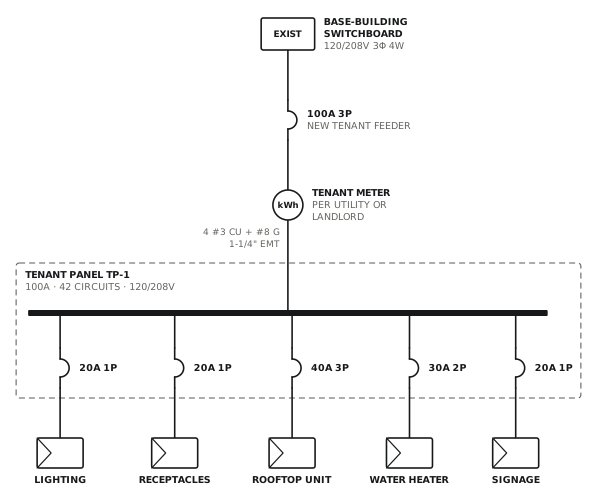
Tenant fit-up panel
New metered 100A feeder and panel from base-building distribution.
CommercialView drawing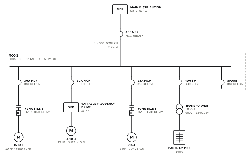
Motor control centre
MCC with starters, a drive, a lighting transformer and a spare bucket.
CommercialView drawingSee all commercial and industrial single line diagrams, or all 52 templates.
Start from this drawing
Free, in the browser, no account. Start from a template or describe the job in plain words, edit the drawing and export a PDF.