Emergency and standby loads on separate transfer switches single line diagram
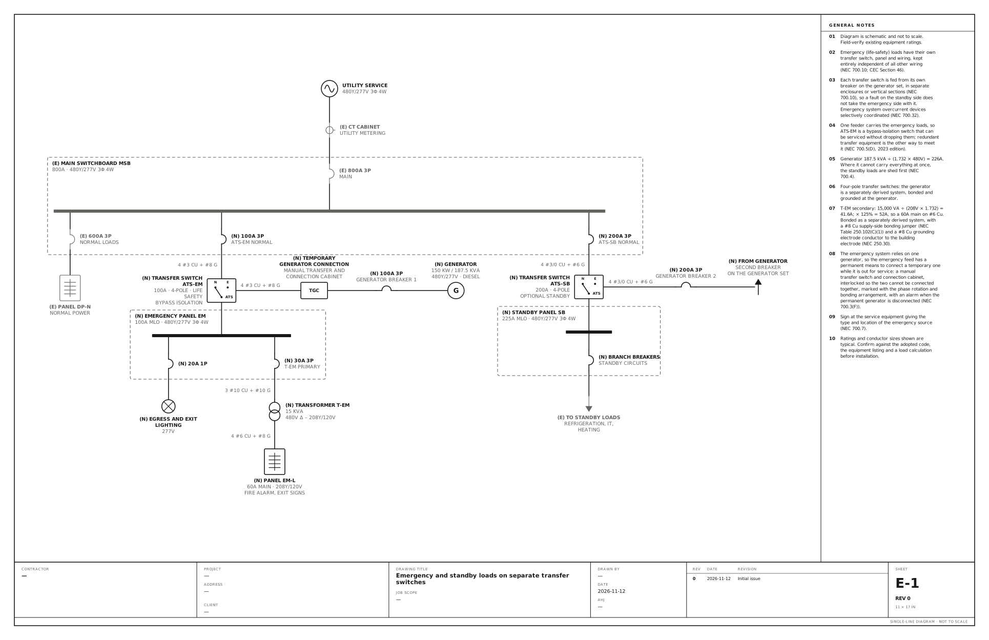
One generator, a life-safety transfer switch and panel, and a second switch for optional standby loads. Use this for a building whose generator supplies both life-safety loads, such as egress lighting and the fire alarm, and loads the owner simply wants kept running. Each kind gets its own transfer switch and panel.
A free template with typical ratings, conductor callouts and general notes. Open it, change what differs on your job, fill in the title block and export a PDF.
Open this template in the editor Download the SVG
What the reviewer checks on this drawing
The reviewer checks that the emergency wiring is kept apart from everything else, that each transfer switch has its own breaker at the generator, the selective coordination of the emergency system, and the connection for a temporary generator.
What the drawing shows
Every device on the sheet, in the order power reaches it.
| Symbol | Label | Rating or detail | Conductors feeding it |
|---|---|---|---|
| Utility source | Utility service | 480Y/277V 3φ 4W | |
| Current transformer | CT cabinet | Utility metering | |
| Circuit breaker | 800A 3P | Main | |
| Panel | Main switchboard MSB | 800A · 480Y/277V 3φ 4W | |
| Circuit breaker | 600A 3P | Normal loads | |
| Panelboard | Panel DP-N | Normal power | |
| Circuit breaker | 100A 3P | ATS-EM normal | |
| Transfer switch | Transfer switch ATS-EM | 100A · 4-pole · life safety, bypass isolation | 4 #3 Cu + #8 G |
| Device | Temporary generator connection (TGC) | Manual transfer and, connection cabinet | 4 #3 Cu + #8 G |
| Circuit breaker | 100A 3P | Generator breaker 1 | |
| Generator | Generator | 150 kW / 187.5 kVA, 480Y/277V · diesel | |
| Panel | Emergency panel EM | 100A MLO · 480Y/277V 3φ 4W | |
| Circuit breaker | 20A 1P | ||
| Lighting | Egress and exit lighting | 277V | |
| Circuit breaker | 30A 3P | T-EM primary | |
| Transformer | Transformer T-EM | 15 kVA, 480V Δ – 208Y/120V | 3 #10 Cu + #10 G |
| Panelboard | Panel EM-L | 60A main · 208Y/120V, Fire alarm, exit signs | 4 #6 Cu + #8 G |
| Circuit breaker | 200A 3P | ATS-SB normal | |
| Transfer switch | Transfer switch ATS-SB | 200A · 4-pole, optional standby | 4 #3/0 Cu + #6 G |
| Circuit breaker | 200A 3P | Generator breaker 2 | 4 #3/0 Cu + #6 G |
| From (continues off sheet) | From generator | Second breaker, on the generator set | |
| Panel | Standby panel SB | 225A MLO · 480Y/277V 3φ 4W | |
| Circuit breaker | Branch breakers | Standby circuits | |
| To (continues off sheet) | To standby loads | Refrigeration, IT, heating |
Notes on the sheet
- Emergency (life-safety) loads have their own transfer switch, panel and wiring, kept entirely independent of all other wiring (NEC 700.10; CEC Section 46).
- Each transfer switch is fed from its own breaker on the generator set, in separate enclosures or vertical sections (NEC 700.10), so a fault on the standby side does not take the emergency side with it. Emergency system overcurrent devices selectively coordinated (NEC 700.32).
- One feeder carries the emergency loads, so ATS-EM is a bypass-isolation switch that can be serviced without dropping them; redundant transfer equipment is the other way to meet it (NEC 700.5(D), 2023 edition).
- Generator 187.5 kVA ÷ (1.732 × 480V) = 226A. Where it cannot carry everything at once, the standby loads are shed first (NEC 700.4).
- Four-pole transfer switches: the generator is a separately derived system, bonded and grounded at the generator.
- T-EM secondary: 15,000 VA ÷ (208V × 1.732) = 41.6A; × 125% = 52A, so a 60A main on #6 Cu. Bonded as a separately derived system, with a #8 Cu supply-side bonding jumper (NEC Table 250.102(C)(1)) and a #8 Cu grounding electrode conductor to the building electrode (NEC 250.30).
- The emergency system relies on one generator, so the emergency feed has a permanent means to connect a temporary one while it is out for service: a manual transfer switch and connection cabinet, interlocked so the two cannot be connected together, marked with the phase rotation and bonding arrangement, with an alarm when the permanent generator is disconnected (NEC 700.3(F)).
- Sign at the service equipment giving the type and location of the emergency source (NEC 700.7).
Diagram is schematic and not to scale. Field-verify existing equipment ratings. Ratings and conductor sizes shown are typical. Confirm against the adopted code, the equipment listing and a load calculation before installation. Code references are to the 2023 NEC and the 2024 Canadian Electrical Code: see references and editions.
Related generator drawings
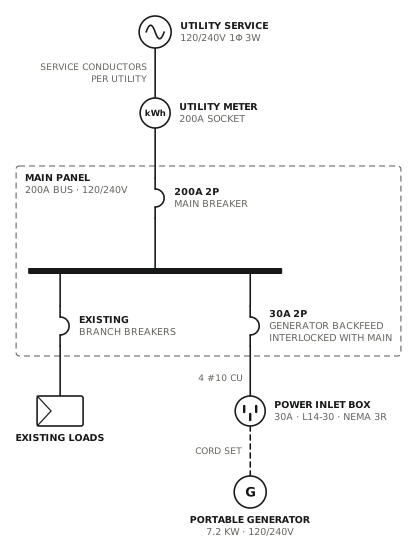
Portable generator inlet with interlock
Backfed 30A breaker mechanically interlocked with the main.
GeneratorView drawing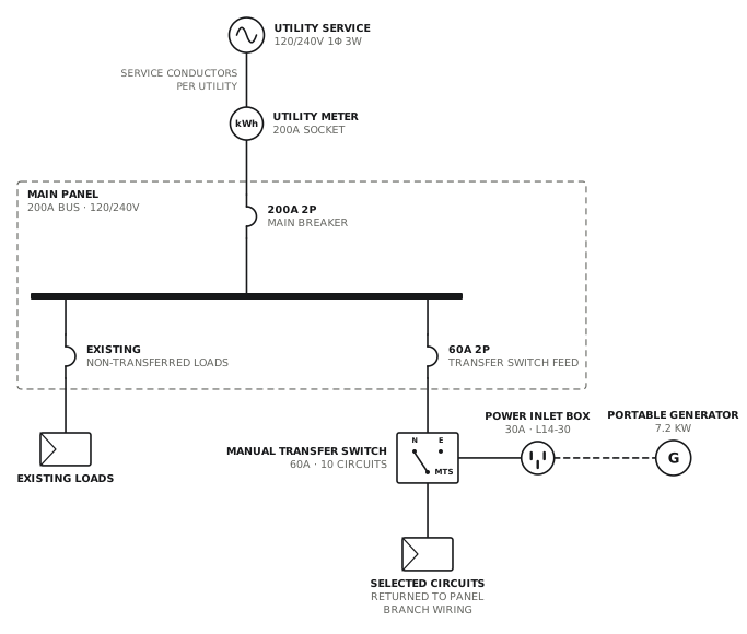
Generator with manual transfer switch
Ten-circuit manual transfer switch with an inlet box.
GeneratorView drawing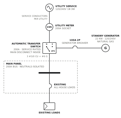
Standby generator, whole-home ATS
Service-rated 200A automatic transfer switch.
GeneratorView drawing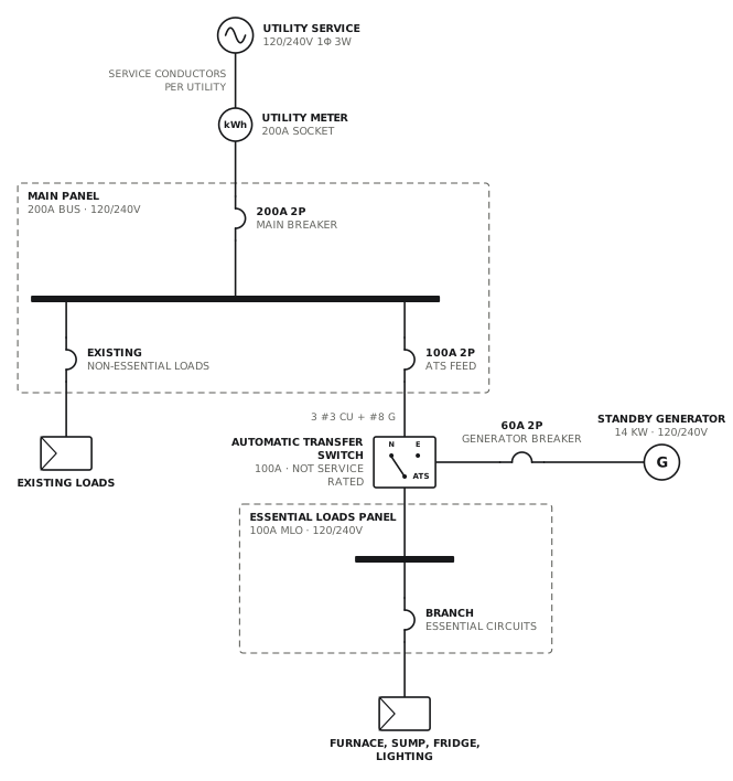
Standby generator, essential loads panel
100A transfer switch feeding an essential loads subpanel.
GeneratorView drawingSee all generator single line diagrams, or all 80 templates.
Start from this drawing
Free, in the browser, no account. Start from a template or describe the job in plain words, edit the drawing and export a PDF.