Generator docking station with manual transfer single line diagram
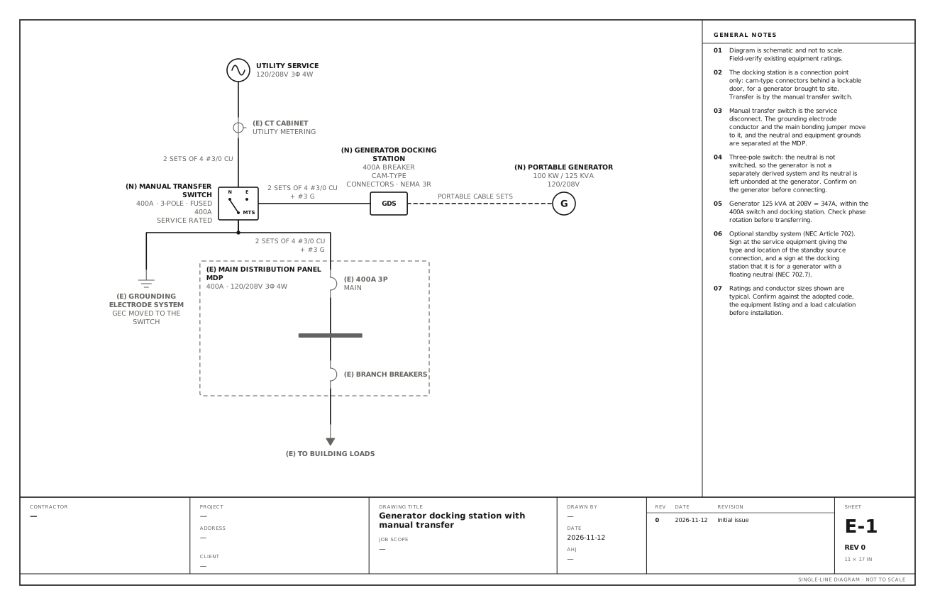
A connection cabinet and a manual transfer switch, ready for a rented generator. Use this for a building that will rent a generator when it needs one: a docking station on the outside wall for the cables, and a manual transfer switch between the utility and the main distribution panel.
A free template with typical ratings, conductor callouts and general notes. Open it, change what differs on your job, fill in the title block and export a PDF.
Open this template in the editor Download the SVG
What the reviewer checks on this drawing
The reviewer checks that transfer is by a listed switch and not by the docking station, the switch as the service disconnect, how the generator neutral is arranged for a three-pole switch, and the sign at the service equipment.
What the drawing shows
Every device on the sheet, in the order power reaches it.
| Symbol | Label | Rating or detail | Conductors feeding it |
|---|---|---|---|
| Utility source | Utility service | 120/208V 3φ 4W | |
| Current transformer | CT cabinet | Utility metering | |
| Transfer switch | Manual transfer switch | 400A · 3-pole · fused 400A, service rated | 2 sets of 4 #3/0 Cu |
| Device | Generator docking station (GDS) | 400A breaker · cam-type, connectors · NEMA 3R | 2 sets of 4 #3/0 Cu, + #3 G |
| Generator | Portable generator | 100 kW / 125 kVA, 120/208V | Portable cable sets |
| Ground | Grounding electrode system | GEC moved to the switch | |
| Circuit breaker | 400A 3P | Main | 2 sets of 4 #3/0 Cu, + #3 G |
| Panel | Main distribution panel MDP | 400A · 120/208V 3φ 4W | |
| Circuit breaker | Branch breakers | ||
| To (continues off sheet) | To building loads |
Notes on the sheet
- The docking station is a connection point only: cam-type connectors behind a lockable door, for a generator brought to site. Transfer is by the manual transfer switch.
- Manual transfer switch is the service disconnect. The grounding electrode conductor and the main bonding jumper move to it, and the neutral and equipment grounds are separated at the MDP.
- Three-pole switch: the neutral is not switched, so the generator is not a separately derived system and its neutral is left unbonded at the generator. Confirm on the generator before connecting.
- Generator 125 kVA at 208V = 347A, within the 400A switch and docking station. Check phase rotation before transferring.
- Optional standby system (NEC Article 702). Sign at the service equipment giving the type and location of the standby source connection, and a sign at the docking station that it is for a generator with a floating neutral (NEC 702.7).
Diagram is schematic and not to scale. Field-verify existing equipment ratings. Ratings and conductor sizes shown are typical. Confirm against the adopted code, the equipment listing and a load calculation before installation. Code references are to the 2023 NEC and the 2024 Canadian Electrical Code: see references and editions.
Related generator drawings
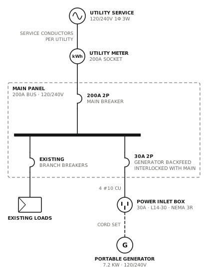
Portable generator inlet with interlock
Backfed 30A breaker mechanically interlocked with the main.
GeneratorView drawing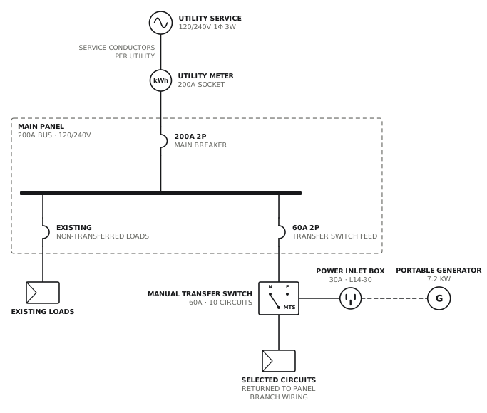
Generator with manual transfer switch
Ten-circuit manual transfer switch with an inlet box.
GeneratorView drawing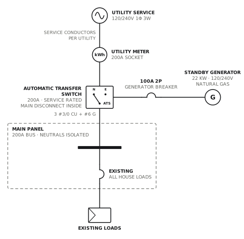
Standby generator, whole-home ATS
Service-rated 200A automatic transfer switch.
GeneratorView drawing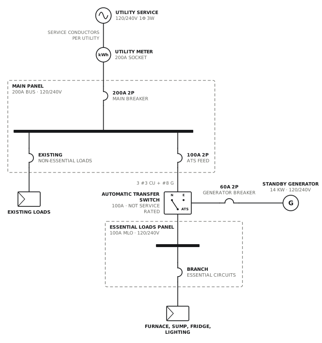
Standby generator, essential loads panel
100A transfer switch feeding an essential loads subpanel.
GeneratorView drawingSee all generator single line diagrams, or all 80 templates.
Start from this drawing
Free, in the browser, no account. Start from a template or describe the job in plain words, edit the drawing and export a PDF.