Multi-family chargers with load management single line diagram
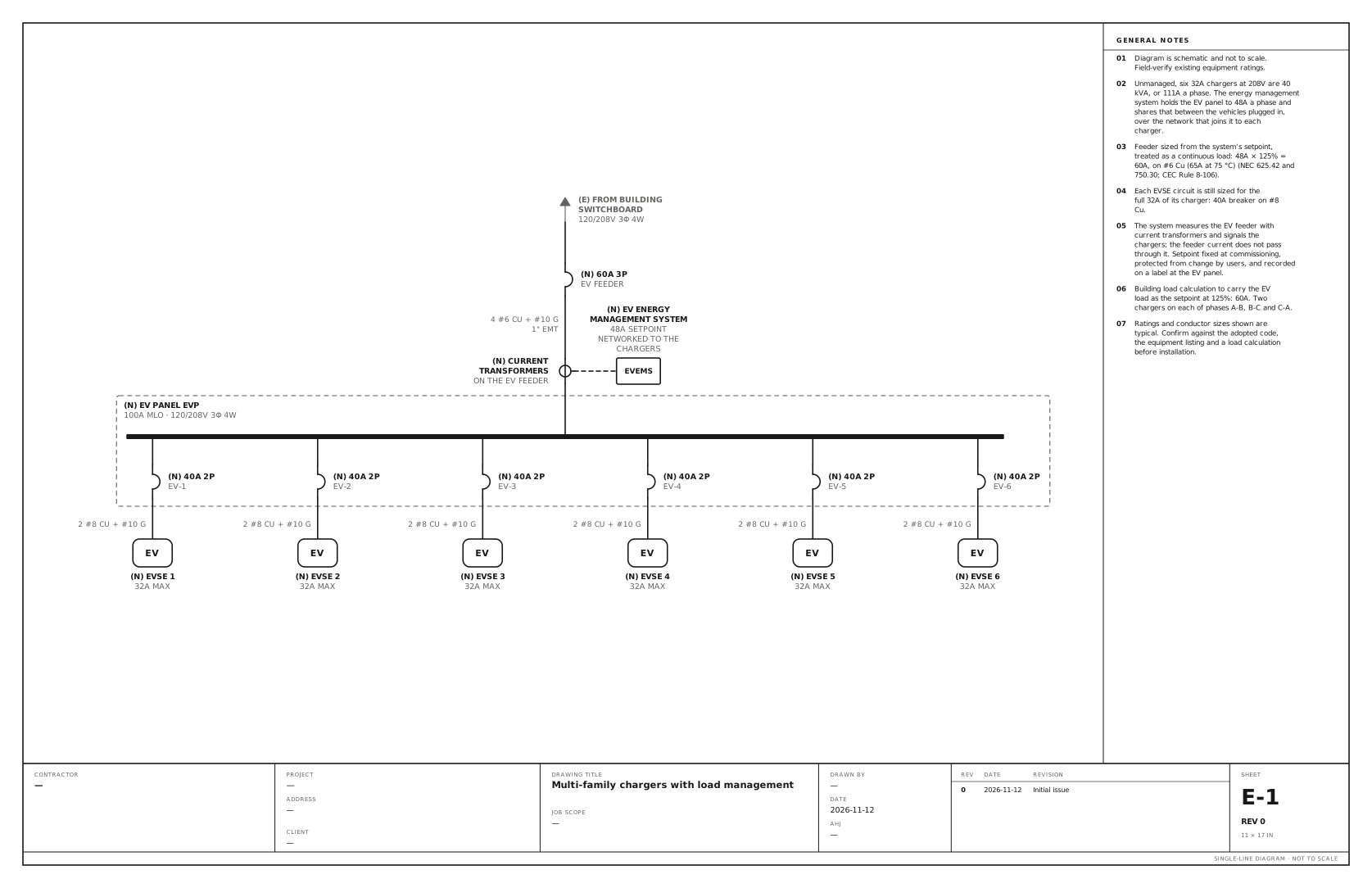
Six chargers share a 60A EV feeder under an energy management system. Use this for a condo or apartment garage where more chargers are wanted than the building has capacity for. A new EV panel takes one feeder, and an energy management system shares its current between the vehicles plugged in.
A free template with typical ratings, conductor callouts and general notes. Open it, change what differs on your job, fill in the title block and export a PDF.
Open this template in the editor Download the SVG
What the reviewer checks on this drawing
The reviewer checks the feeder against the system’s setpoint at 125%, where the current is measured, that the setpoint cannot be changed by users, and the building load calculation with the setpoint carried as the EV load.
What the drawing shows
Every device on the sheet, in the order power reaches it.
| Symbol | Label | Rating or detail | Conductors feeding it |
|---|---|---|---|
| From (continues off sheet) | From building switchboard | 120/208V 3φ 4W | |
| Circuit breaker | 60A 3P | EV feeder | |
| Current transformer | Current transformers | On the EV feeder | 4 #6 Cu + #10 G, 1" EMT |
| Device | EV energy management system (EVEMS) | 48A setpoint, networked to the chargers | |
| Panel | EV panel EVP | 100A MLO · 120/208V 3φ 4W | |
| Circuit breaker | 40A 2P | EV-1 | |
| EV charger | EVSE 1 | 32A max | 2 #8 Cu + #10 G |
| Circuit breaker | 40A 2P | EV-2 | |
| EV charger | EVSE 2 | 32A max | 2 #8 Cu + #10 G |
| Circuit breaker | 40A 2P | EV-3 | |
| EV charger | EVSE 3 | 32A max | 2 #8 Cu + #10 G |
| Circuit breaker | 40A 2P | EV-4 | |
| EV charger | EVSE 4 | 32A max | 2 #8 Cu + #10 G |
| Circuit breaker | 40A 2P | EV-5 | |
| EV charger | EVSE 5 | 32A max | 2 #8 Cu + #10 G |
| Circuit breaker | 40A 2P | EV-6 | |
| EV charger | EVSE 6 | 32A max | 2 #8 Cu + #10 G |
Notes on the sheet
- Unmanaged, six 32A chargers at 208V are 40 kVA, or 111A a phase. The energy management system holds the EV panel to 48A a phase and shares that between the vehicles plugged in, over the network that joins it to each charger.
- Feeder sized from the system’s setpoint, treated as a continuous load: 48A × 125% = 60A, on #6 Cu (65A at 75 °C) (NEC 625.42 and 750.30; CEC Rule 8-106).
- Each EVSE circuit is still sized for the full 32A of its charger: 40A breaker on #8 Cu.
- The system measures the EV feeder with current transformers and signals the chargers; the feeder current does not pass through it. Setpoint fixed at commissioning, protected from change by users, and recorded on a label at the EV panel.
- Building load calculation to carry the EV load as the setpoint at 125%: 60A. Two chargers on each of phases A-B, B-C and C-A.
Diagram is schematic and not to scale. Field-verify existing equipment ratings. Ratings and conductor sizes shown are typical. Confirm against the adopted code, the equipment listing and a load calculation before installation. Code references are to the 2023 NEC and the 2024 Canadian Electrical Code: see references and editions.
Related EV charger drawings
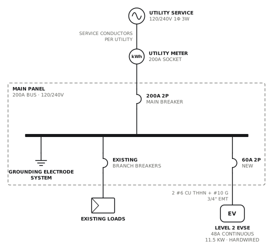
Level 2 charger from main panel
Dedicated 60A circuit to a hardwired 48A charger.
EVView drawing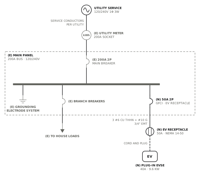
EV receptacle, NEMA 14-50
50A GFCI circuit to a 14-50 receptacle for a plug-in charger.
EVView drawing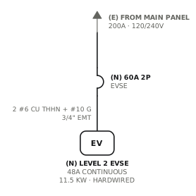
Level 2 charger, new work only
Only the new circuit, starting at an arrow from the main panel.
EVView drawing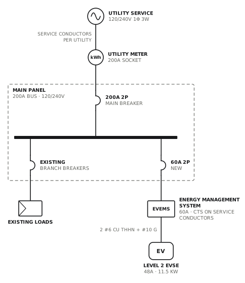
Level 2 charger with load management
Energy management system sheds the charger when the service is near its limit.
EVView drawingSee all EV charger single line diagrams, or all 80 templates.
Start from this drawing
Free, in the browser, no account. Start from a template or describe the job in plain words, edit the drawing and export a PDF.