DC fast charging site single line diagram
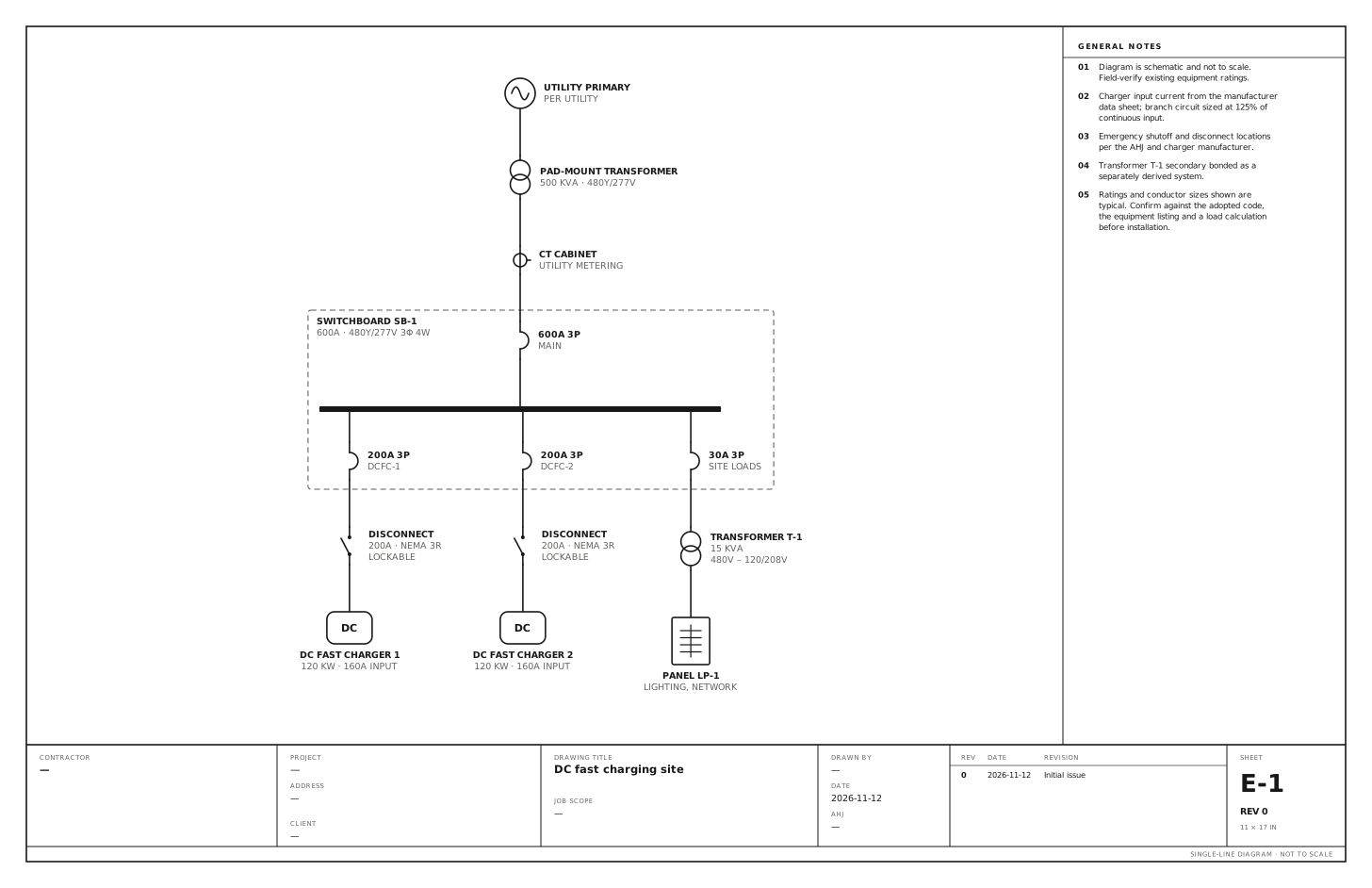
Dedicated 480V service with two 120 kW chargers and a site-loads transformer. Use this for a DC fast charging site with its own utility service: a transformer, a 480V switchboard, the chargers, and a small transformer for the site loads.
A free template with typical ratings, conductor callouts and general notes. Open it, change what differs on your job, fill in the title block and export a PDF.
Open this template in the editor Download the SVG
What the reviewer checks on this drawing
The reviewer checks charger input current taken from the manufacturer’s data sheet with the branch circuits at 125%, the emergency shutoff and disconnect locations, and the bonding of the site-loads transformer as a separately derived system.
What the drawing shows
Every device on the sheet, in the order power reaches it.
| Symbol | Label | Rating or detail |
|---|---|---|
| Utility source | Utility primary | Per utility |
| Transformer | Pad-mount transformer | 500 kVA · 480Y/277V |
| Current transformer | CT cabinet | Utility metering |
| Circuit breaker | 600A 3P | Main |
| Panel | Switchboard SB-1 | 600A · 480Y/277V 3φ 4W |
| Circuit breaker | 200A 3P | DCFC-1 |
| Disconnect switch | Disconnect | 200A · NEMA 3R, lockable |
| EV charger | DC fast charger 1 | 120 kW · 160A input |
| Circuit breaker | 200A 3P | DCFC-2 |
| Disconnect switch | Disconnect | 200A · NEMA 3R, lockable |
| EV charger | DC fast charger 2 | 120 kW · 160A input |
| Circuit breaker | 30A 3P | Site loads |
| Transformer | Transformer T-1 | 15 kVA, 480V – 120/208V |
| Panelboard | Panel LP-1 | Lighting, network |
Notes on the sheet
- Charger input current from the manufacturer data sheet; branch circuit sized at 125% of continuous input.
- Emergency shutoff and disconnect locations per the AHJ and charger manufacturer.
- Transformer T-1 secondary bonded as a separately derived system.
Diagram is schematic and not to scale. Field-verify existing equipment ratings. Ratings and conductor sizes shown are typical. Confirm against the adopted code, the equipment listing and a load calculation before installation. Code references are to the 2023 NEC and the 2024 Canadian Electrical Code: see references and editions.
Related EV charger drawings
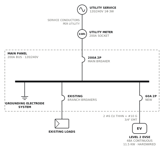
Level 2 charger from main panel
Dedicated 60A circuit to a hardwired 48A charger.
EVView drawing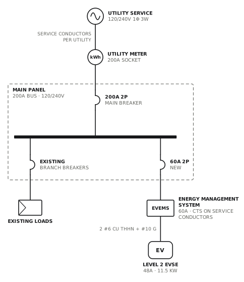
Level 2 charger with load management
Energy management system sheds the charger when the service is near its limit.
EVView drawing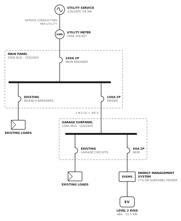
Charger from subpanel with load management
Garage subpanel feeds the charger through an energy management system.
EVView drawing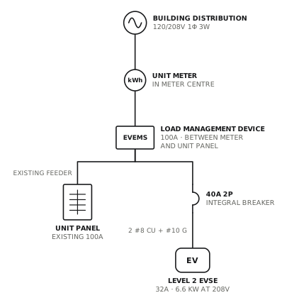
Condo charger from meter with load miser
Load management device between the unit meter and unit panel feeds the charger.
EVView drawingSee all EV charger single line diagrams, or all 40 templates.
Start from this drawing
Free, in the browser, no account. Start from a template or describe the job in plain words, edit the drawing and export a PDF.