Pool equipment subpanel single line diagram
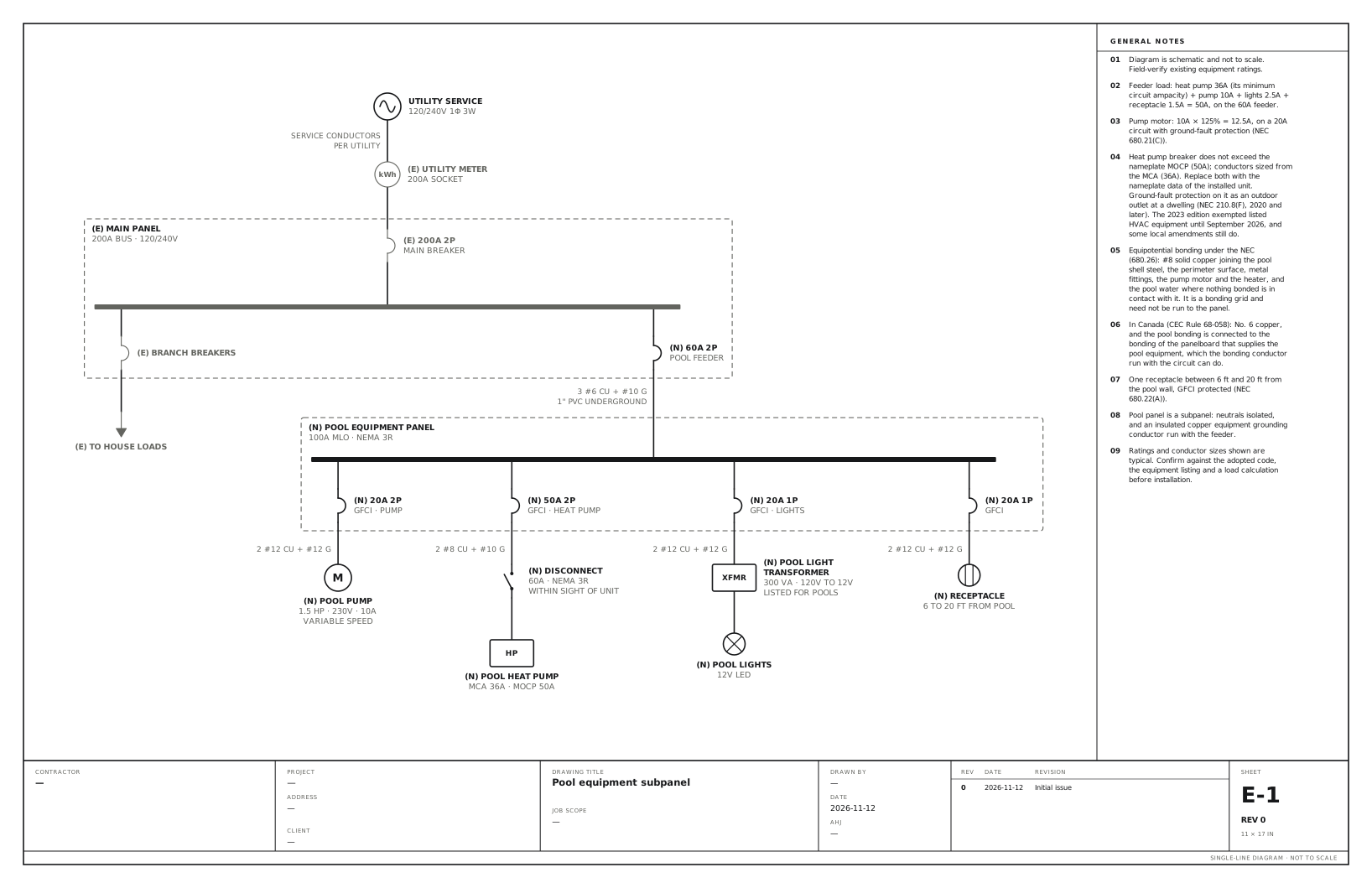
A 60A feeder to a panel at the equipment pad for the pump, heat pump, lights and a receptacle. Use this for a swimming pool with its own panel at the equipment pad, feeding the pump, a heat pump, the pool lights and a receptacle.
A free template with typical ratings, conductor callouts and general notes. Open it, change what differs on your job, fill in the title block and export a PDF.
Open this template in the editor Download the SVG
What the reviewer checks on this drawing
The inspector checks ground-fault protection on the pump, the heat pump, the lights and the receptacle, the equipotential bonding grid, the feeder with an insulated equipment grounding conductor, and where the receptacle is relative to the water.
What the drawing shows
Every device on the sheet, in the order power reaches it.
| Symbol | Label | Rating or detail | Conductors feeding it |
|---|---|---|---|
| Utility source | Utility service | 120/240V 1φ 3W | |
| Meter | Utility meter | 200A socket | Service conductors, per utility |
| Circuit breaker | 200A 2P | Main breaker | |
| Panel | Main panel | 200A bus · 120/240V | |
| Circuit breaker | Branch breakers | ||
| To (continues off sheet) | To house loads | ||
| Circuit breaker | 60A 2P | Pool feeder | |
| Panel | Pool equipment panel | 100A MLO · NEMA 3R | 3 #6 Cu + #10 G, 1" PVC underground |
| Circuit breaker | 20A 2P | GFCI · pump | |
| Motor | Pool pump | 1.5 HP · 230V · 10A, variable speed | 2 #12 Cu + #12 G |
| Circuit breaker | 50A 2P | GFCI · heat pump | |
| Disconnect switch | Disconnect | 60A · NEMA 3R, within sight of unit | 2 #8 Cu + #10 G |
| Device | Pool heat pump (HP) | MCA 36A · MOCP 50A | |
| Circuit breaker | 20A 1P | GFCI · lights | |
| Device | Pool light transformer (XFMR) | 300 VA · 120V to 12V, listed for pools | 2 #12 Cu + #12 G |
| Lighting | Pool lights | 12V LED | |
| Circuit breaker | 20A 1P | GFCI | |
| Receptacle | Receptacle | 6 to 20 ft from pool | 2 #12 Cu + #12 G |
Notes on the sheet
- Feeder load: heat pump 36A (its minimum circuit ampacity) + pump 10A + lights 2.5A + receptacle 1.5A = 50A, on the 60A feeder.
- Pump motor: 10A × 125% = 12.5A, on a 20A circuit with ground-fault protection (NEC 680.21(C)).
- Heat pump breaker does not exceed the nameplate MOCP (50A); conductors sized from the MCA (36A). Replace both with the nameplate data of the installed unit. Ground-fault protection on it as an outdoor outlet at a dwelling (NEC 210.8(F), 2020 and later). The 2023 edition exempted listed HVAC equipment until September 2026, and some local amendments still do.
- Equipotential bonding under the NEC (680.26): #8 solid copper joining the pool shell steel, the perimeter surface, metal fittings, the pump motor and the heater, and the pool water where nothing bonded is in contact with it. It is a bonding grid and need not be run to the panel.
- In Canada (CEC Rule 68-058): No. 6 copper, and the pool bonding is connected to the bonding of the panelboard that supplies the pool equipment, which the bonding conductor run with the circuit can do.
- One receptacle between 6 ft and 20 ft from the pool wall, GFCI protected (NEC 680.22(A)).
- Pool panel is a subpanel: neutrals isolated, and an insulated copper equipment grounding conductor run with the feeder.
Diagram is schematic and not to scale. Field-verify existing equipment ratings. Ratings and conductor sizes shown are typical. Confirm against the adopted code, the equipment listing and a load calculation before installation. Code references are to the 2023 NEC and the 2024 Canadian Electrical Code: see references and editions.
Related service and panel drawings
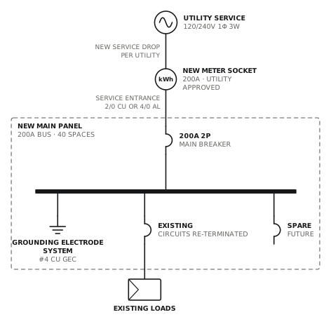
Service and main panel upgrade to 200A
New meter socket, service entrance and 200A panel with surge protection.
ServiceView drawing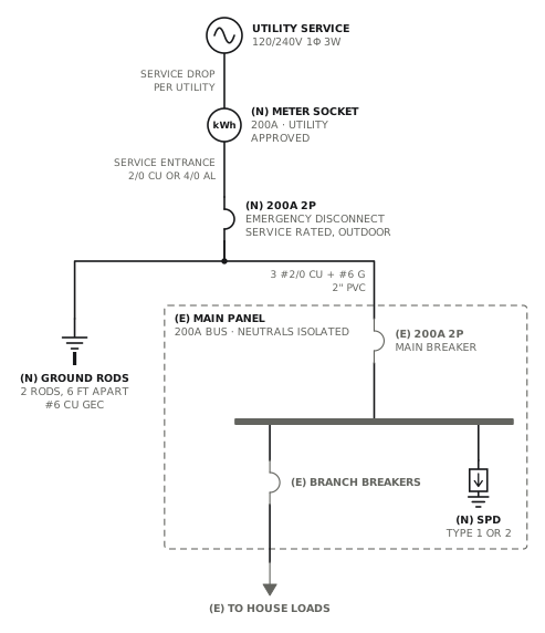
Service upgrade with outdoor emergency disconnect
New meter socket and outdoor service disconnect; the panel inside stays and becomes a subpanel.
ServiceView drawing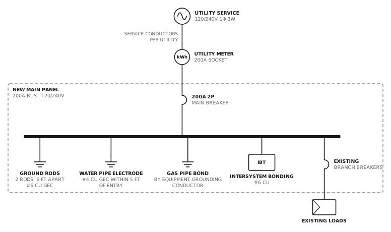
Panel upgrade with grounding system replacement
New panel with rods, water bond, intersystem bonding and surge protection.
ServiceView drawing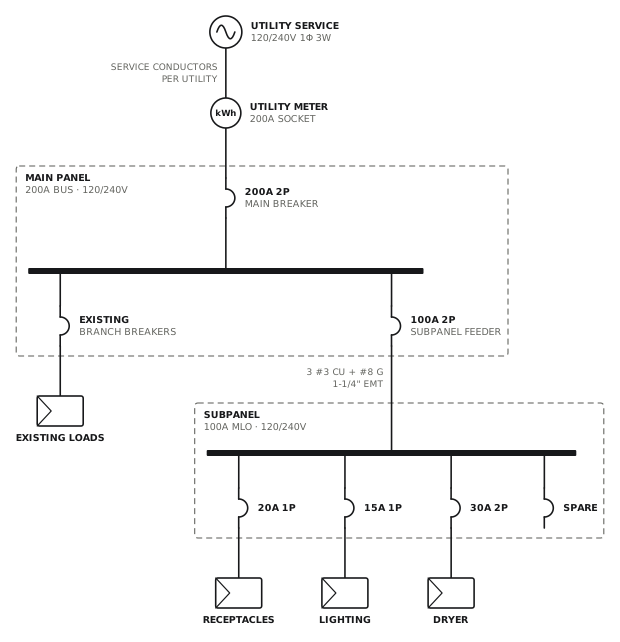
Subpanel addition
100A four-wire feeder to a new subpanel.
ServiceView drawingSee all service and panel single line diagrams, or all 80 templates.
Start from this drawing
Free, in the browser, no account. Start from a template or describe the job in plain words, edit the drawing and export a PDF.