Rotary phase converter for a shop single line diagram
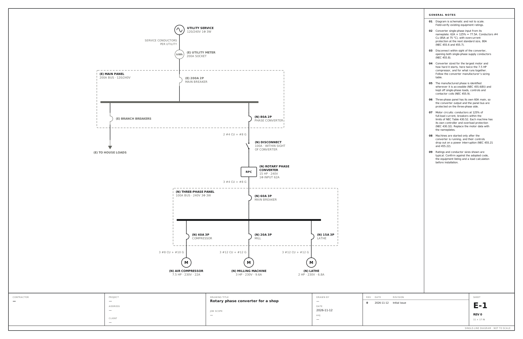
Three-phase machines run from a single-phase service through a 15 HP converter and its own panel. Use this for a shop with three-phase machines and only single-phase power: a rotary phase converter on its own breaker and disconnect, feeding a three-phase panel for the machines.
A free template with typical ratings, conductor callouts and general notes. Open it, change what differs on your job, fill in the title block and export a PDF.
Open this template in the editor Download the SVG
What the reviewer checks on this drawing
The inspector checks the conductors and breaker against the converter’s nameplate input current, the disconnect within sight of the converter, and that nothing single-phase is connected to the manufactured phase.
What the drawing shows
Every device on the sheet, in the order power reaches it.
| Symbol | Label | Rating or detail | Conductors feeding it |
|---|---|---|---|
| Utility source | Utility service | 120/240V 1φ 3W | |
| Meter | Utility meter | 200A socket | Service conductors, per utility |
| Circuit breaker | 200A 2P | Main breaker | |
| Panel | Main panel | 200A bus · 120/240V | |
| Circuit breaker | Branch breakers | ||
| To (continues off sheet) | To house loads | ||
| Circuit breaker | 80A 2P | Phase converter | |
| Disconnect switch | Disconnect | 100A · within sight, of converter | 2 #4 Cu + #8 G |
| Device | Rotary phase converter (RPC) | 15 HP · 240V, 1φ input 62A | |
| Circuit breaker | 60A 3P | Main breaker | 3 #4 Cu + #8 G |
| Panel | Three-phase panel | 100A bus · 240V 3φ 3W | |
| Circuit breaker | 40A 3P | Compressor | |
| Motor | Air compressor | 7.5 HP · 230V · 22A | 3 #8 Cu + #10 G |
| Circuit breaker | 20A 3P | Mill | |
| Motor | Milling machine | 3 HP · 230V · 9.6A | 3 #12 Cu + #12 G |
| Circuit breaker | 15A 3P | Lathe | |
| Motor | Lathe | 2 HP · 230V · 6.8A | 3 #12 Cu + #12 G |
Notes on the sheet
- Converter single-phase input from its nameplate: 62A × 125% = 77.5A. Conductors #4 Cu (85A at 75 °C), with overcurrent protection at the next standard size, 80A (NEC 455.6 and 455.7).
- Disconnect within sight of the converter, opening both single-phase supply conductors (NEC 455.8).
- Converter sized for the largest motor and how hard it starts, here twice the 7.5 HP compressor, and for what runs together. Follow the converter manufacturer’s sizing table.
- The manufactured phase is identified wherever it is accessible (NEC 455.6(B)) and kept off single-phase loads, controls and contactor coils (NEC 455.9).
- Three-phase panel has its own 60A main, so the converter output and the panel bus are protected on the three-phase side.
- Motor circuits: conductors at 125% of full-load current, breakers within the limits of NEC Table 430.52. Each machine has its own controller and overload protection (NEC 430.32). Replace the motor data with the nameplates.
- Machines are started only after the converter is running, and their controls drop out on a power interruption (NEC 455.21 and 455.22).
Diagram is schematic and not to scale. Field-verify existing equipment ratings. Ratings and conductor sizes shown are typical. Confirm against the adopted code, the equipment listing and a load calculation before installation. Code references are to the 2023 NEC and the 2024 Canadian Electrical Code: see references and editions.
Related service and panel drawings
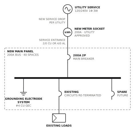
Service and main panel upgrade to 200A
New meter socket, service entrance and 200A panel with surge protection.
ServiceView drawing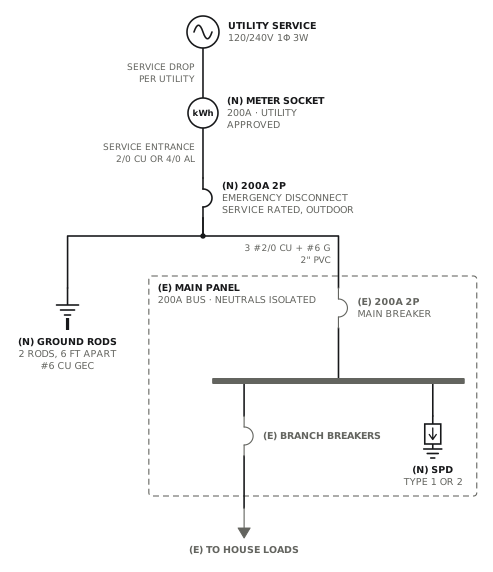
Service upgrade with outdoor emergency disconnect
New meter socket and outdoor service disconnect; the panel inside stays and becomes a subpanel.
ServiceView drawing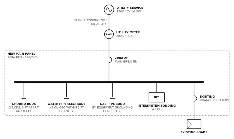
Panel upgrade with grounding system replacement
New panel with rods, water bond, intersystem bonding and surge protection.
ServiceView drawing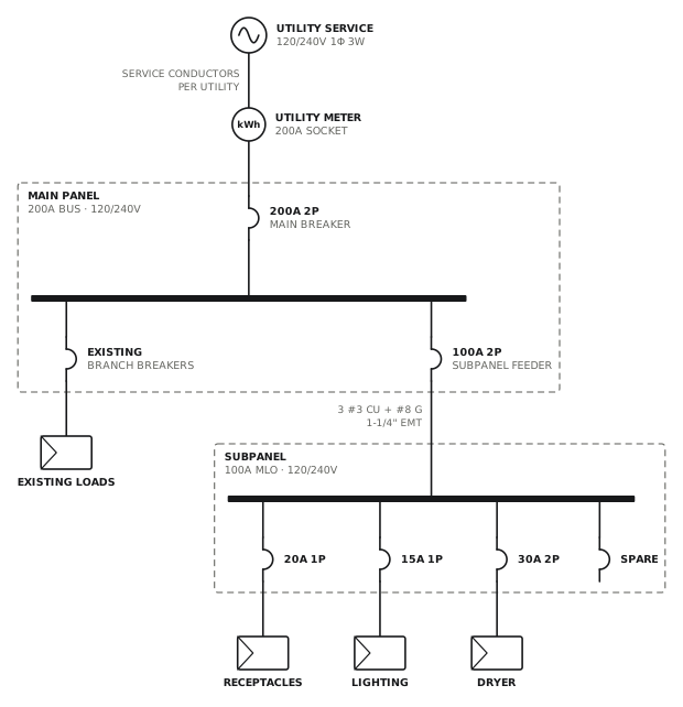
Subpanel addition
100A four-wire feeder to a new subpanel.
ServiceView drawingSee all service and panel single line diagrams, or all 80 templates.
Start from this drawing
Free, in the browser, no account. Start from a template or describe the job in plain words, edit the drawing and export a PDF.