Farm service with yard pole and generator switch single line diagram
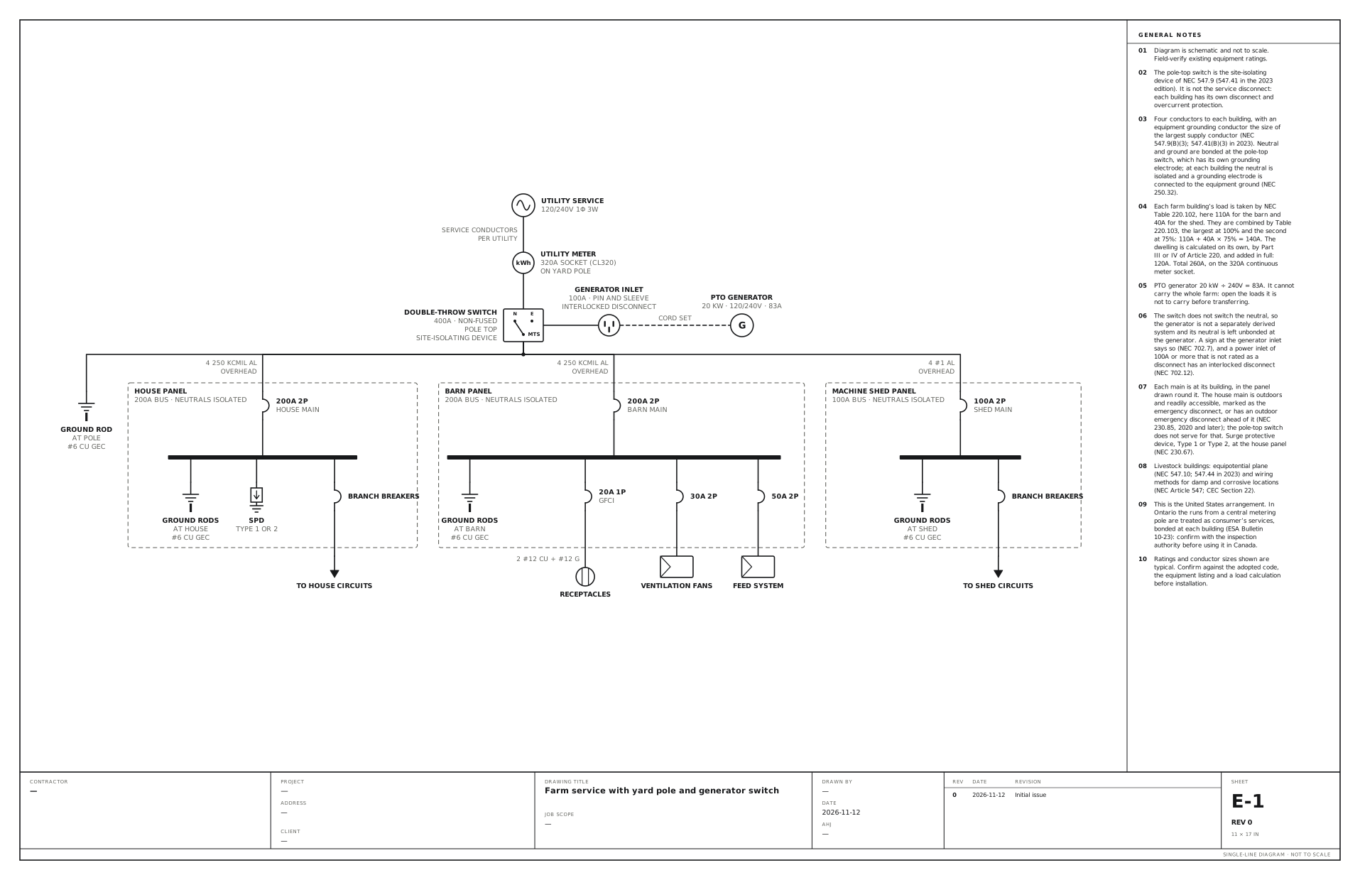
A metered yard pole with a double-throw switch for a PTO generator, feeding the house, the barn and a shed. Use this for a farm fed from a metered yard pole, with a pole-top double-throw switch for a tractor-driven generator and overhead runs to the house, the barn and a machine shed.
A free template with typical ratings, conductor callouts and general notes. Open it, change what differs on your job, fill in the title block and export a PDF.
Open this template in the editor Download the SVG
What the reviewer checks on this drawing
The inspector checks the disconnect and overcurrent protection at each building, the emergency disconnect at the house, the four-wire runs with a full-size ground, where the neutral is bonded, the grounding electrode at the pole and at each building, and the farm load calculation.
What the drawing shows
Every device on the sheet, in the order power reaches it.
| Symbol | Label | Rating or detail | Conductors feeding it |
|---|---|---|---|
| Utility source | Utility service | 120/240V 1φ 3W | |
| Meter | Utility meter | 320A socket (CL320), on yard pole | Service conductors, per utility |
| Transfer switch | Double-throw switch | 400A · non-fused · pole top, site-isolating device | |
| Power inlet | Generator inlet | 100A · pin and sleeve, interlocked disconnect | |
| Generator | PTO generator | 20 kW · 120/240V · 83A | Cord set |
| Grounding electrode | Ground rod | At pole, #6 Cu GEC | |
| Circuit breaker | 200A 2P | House main | 4 250 kcmil Al, overhead |
| Panel | House panel | 200A bus · neutrals isolated | |
| Grounding electrode | Ground rods | At house, #6 Cu GEC | |
| Surge protective device | SPD | Type 1 or 2 | |
| Circuit breaker | Branch breakers | ||
| To (continues off sheet) | To house circuits | ||
| Circuit breaker | 200A 2P | Barn main | 4 250 kcmil Al, overhead |
| Panel | Barn panel | 200A bus · neutrals isolated | |
| Grounding electrode | Ground rods | At barn, #6 Cu GEC | |
| Circuit breaker | 20A 1P | GFCI | |
| Receptacle | Receptacles | 2 #12 Cu + #12 G | |
| Circuit breaker | 30A 2P | ||
| Load | Ventilation fans | ||
| Circuit breaker | 50A 2P | ||
| Load | Feed system | ||
| Circuit breaker | 100A 2P | Shed main | 4 #1 Al, overhead |
| Panel | Machine shed panel | 100A bus · neutrals isolated | |
| Grounding electrode | Ground rods | At shed, #6 Cu GEC | |
| Circuit breaker | Branch breakers | ||
| To (continues off sheet) | To shed circuits |
Notes on the sheet
- The pole-top switch is the site-isolating device of NEC 547.9 (547.41 in the 2023 edition). It is not the service disconnect: each building has its own disconnect and overcurrent protection.
- Four conductors to each building, with an equipment grounding conductor the size of the largest supply conductor (NEC 547.9(B)(3); 547.41(B)(3) in 2023). Neutral and ground are bonded at the pole-top switch, which has its own grounding electrode; at each building the neutral is isolated and a grounding electrode is connected to the equipment ground (NEC 250.32).
- Each farm building’s load is taken by NEC Table 220.102, here 110A for the barn and 40A for the shed. They are combined by Table 220.103, the largest at 100% and the second at 75%: 110A + 40A × 75% = 140A. The dwelling is calculated on its own, by Part III or IV of Article 220, and added in full: 120A. Total 260A, on the 320A continuous meter socket.
- PTO generator 20 kW ÷ 240V = 83A. It cannot carry the whole farm: open the loads it is not to carry before transferring.
- The switch does not switch the neutral, so the generator is not a separately derived system and its neutral is left unbonded at the generator. A sign at the generator inlet says so (NEC 702.7), and a power inlet of 100A or more that is not rated as a disconnect has an interlocked disconnect (NEC 702.12).
- Each main is at its building, in the panel drawn round it. The house main is outdoors and readily accessible, marked as the emergency disconnect, or has an outdoor emergency disconnect ahead of it (NEC 230.85, 2020 and later); the pole-top switch does not serve for that. Surge protective device, Type 1 or Type 2, at the house panel (NEC 230.67).
- Livestock buildings: equipotential plane (NEC 547.10; 547.44 in 2023) and wiring methods for damp and corrosive locations (NEC Article 547; CEC Section 22).
- This is the United States arrangement. In Ontario the runs from a central metering pole are treated as consumer’s services, bonded at each building (ESA Bulletin 10-23): confirm with the inspection authority before using it in Canada.
Diagram is schematic and not to scale. Field-verify existing equipment ratings. Ratings and conductor sizes shown are typical. Confirm against the adopted code, the equipment listing and a load calculation before installation. Code references are to the 2023 NEC and the 2024 Canadian Electrical Code: see references and editions.
Related service and panel drawings
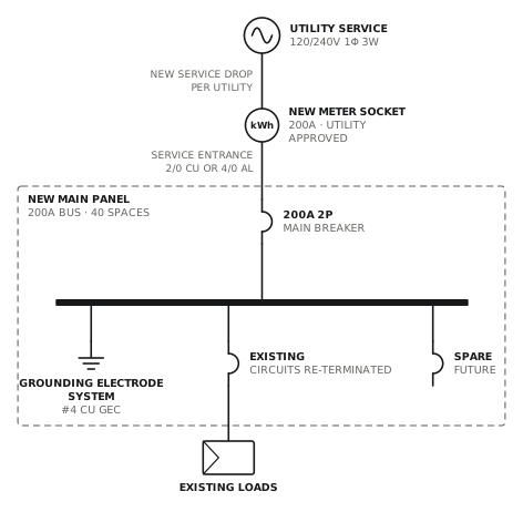
Service and main panel upgrade to 200A
New meter socket, service entrance and 200A panel with surge protection.
ServiceView drawing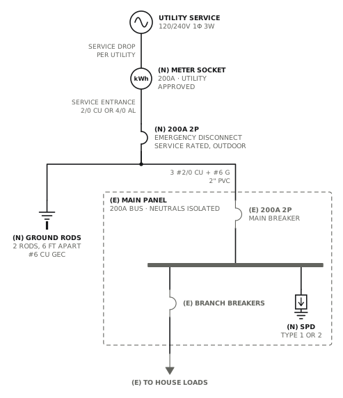
Service upgrade with outdoor emergency disconnect
New meter socket and outdoor service disconnect; the panel inside stays and becomes a subpanel.
ServiceView drawing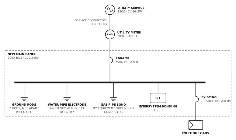
Panel upgrade with grounding system replacement
New panel with rods, water bond, intersystem bonding and surge protection.
ServiceView drawing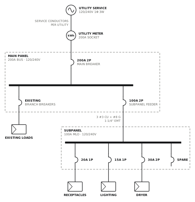
Subpanel addition
100A four-wire feeder to a new subpanel.
ServiceView drawingSee all service and panel single line diagrams, or all 80 templates.
Start from this drawing
Free, in the browser, no account. Start from a template or describe the job in plain words, edit the drawing and export a PDF.